
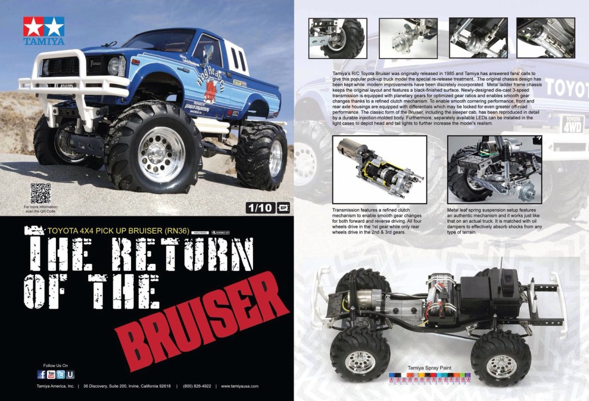
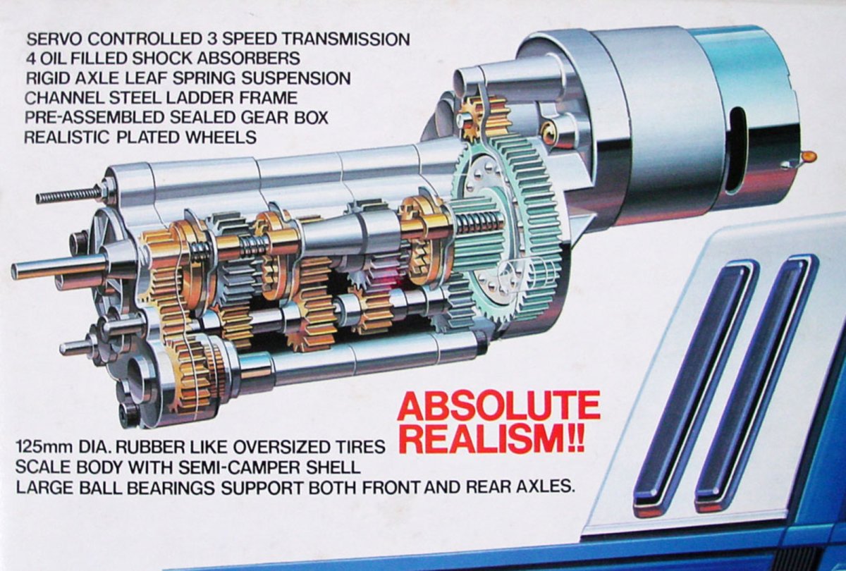
 Tamiya released the 58048 Bruiser in August of 1985 and, at the time, it was an absolute revolution. All metal chassis, 3-speed transmission, oil filled shocks, 4WD with shifting transfer case, real leaf springs, this model had it all. The problem was that it also cost 39,000¥ or $350 at the current exchange rate, perhaps twice that much adjusted for inflation. That put it completely out of reach for most kids. But in March of 2012, 27 years later, Tamiya re-released this classic this time at 89,800¥. So it wasn't any cheaper than before, but the people who wanted it had grown up and had more money now. The updated model replaced the old 750 sized motor with a more moderate 540 and also updated the transmission considerably. Of course the old mechanical speed controller was replaced with an ESC, but other than that this model is much like it was decades ago.
I managed to get ahold of one in 2017 and couldn't have been happier with the build. This is a pretty complex assembly project with loads of metal, hundreds of fasteners, plenty of painting, and anything else you could want out of an RC project. The final model is a bit hard to categorize. It is certainly a scale model and uses a hard body rendition of an RN36 type Toyota Hilux. The tires are obviously much larger than stock, and the suspension is considerably lifted as well. The finished model is certainly not fast, but neither is it a crawler. It is not a monster truck, so what is it? I don't know, it's just awesome. It is a scale cruiser and works great on pavement, on grass, or on the trail. With open front and rear differentials the off road performance isn't great even in 4WD. You can lock the differentials manually, but then it is no good on road. I used anti-wear grease in the diffs for a happy medium. The 3-speed transmission is really the star of the show and shifts on the fly. Multiple speeds are not strictly necessary with electric, but it makes low speed crawling quite pleasant and high gear is fun on the road. With leaf springs and fat tires, this thing bounces around plenty. As of this writing many upgrades are available and I installed plenty of them. I used relatively inexpensive analog Futaba servos and the stock ESC, but I replaced the silver can 540 motor with a moderate brushless motor. I also added lots of lights and some additional interior details. Battery space is limited so a 7.2V NiMH works best. You can read about the whole experience in my build journal below.
Building the Frame
The Bruiser has quite an impressive box. It is big and heavy with retro box art. Sadly, I did not take any pictures of the inside of the box. Everything inside is nicely arranged with some blister packaging highlighting key parts. I flattened the cover and saved it because I may frame it some day. This model is too special to just discard the packaging.

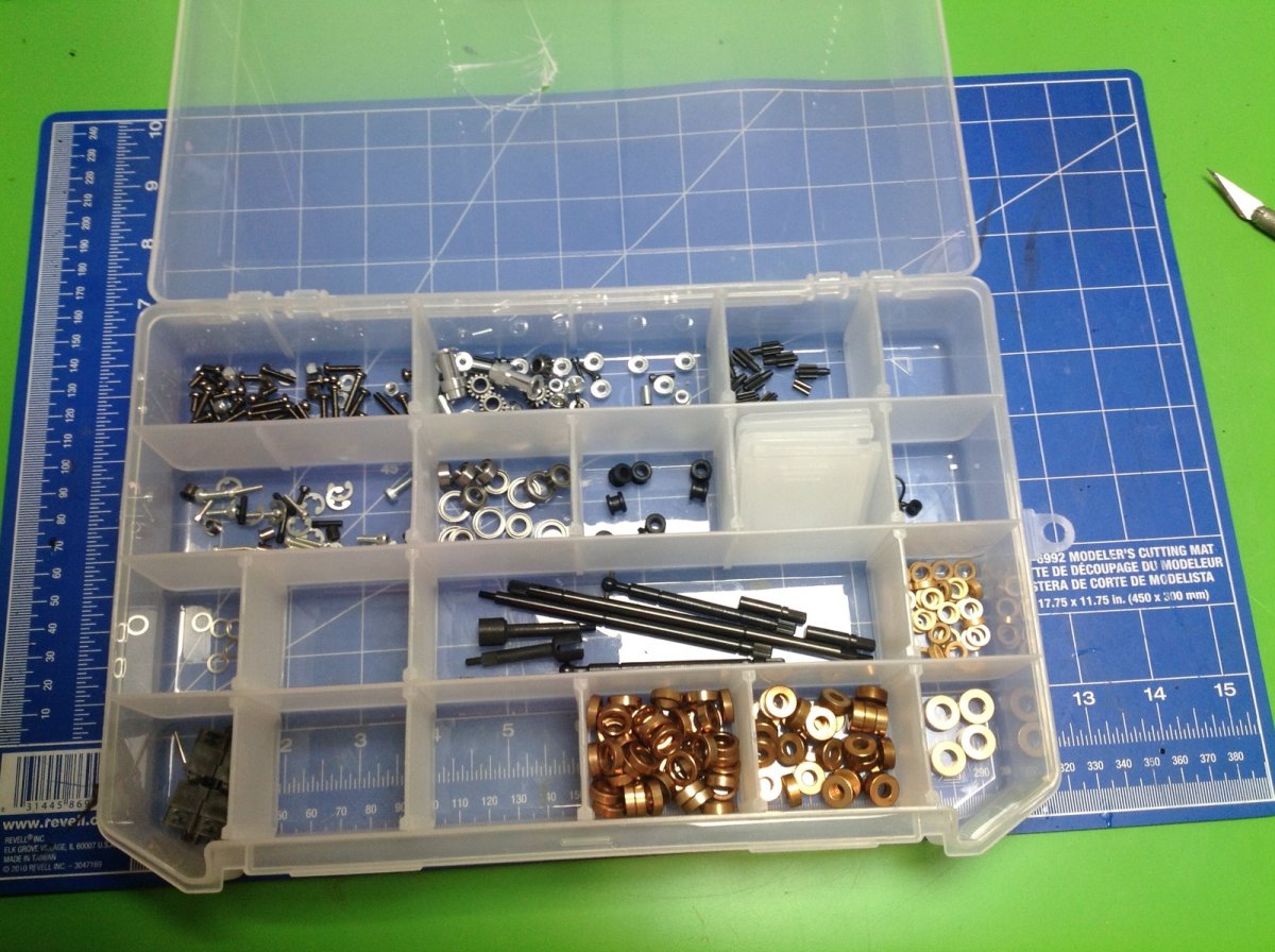
There is a lot of hardware inside. There are 5 bags labelled A-E which contain the bulk of the fasteners and loose metal parts. Others are contained in a blister pack in the box. I emptied the hardware from each bag into a separate slot in my plastic case so I could access everything more easily. The huge pile of metal bushings you see are actually from the King Hauler, not from this model. The Bruiser comes with full ball bearings.
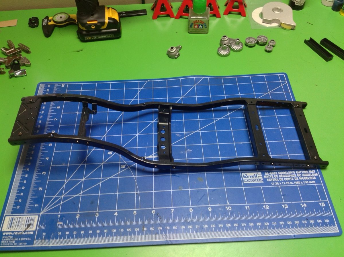
Step 1 starts right out with the frame rails and connects them will all metal cross members. Since virtually this entire kit is metal, using thread lock is very important. The kit includes some red gel type thread lock, enough to do the whole model. It works a little differently than regular blue liquid thread lock, but is actually easier to apply in my opinion. The second step starts adding brackets for the upper shock mounts.
Steps 3 and 4 add shackles for the leaf springs and a crank arm for the steering. At this point the only plastic part is that white steering crank. Keep that in mind for later, because it is really the only weak link on the model and is not nearly stiff enough to properly control the steering. It is made from the same very soft frangible plastic as the bumpers (and the other white parts). You can see the rubber grommets at the top of the damper stays which will cushion impacts. This model is full of little details like that.
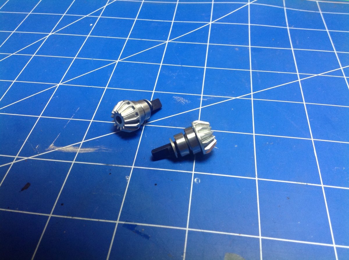
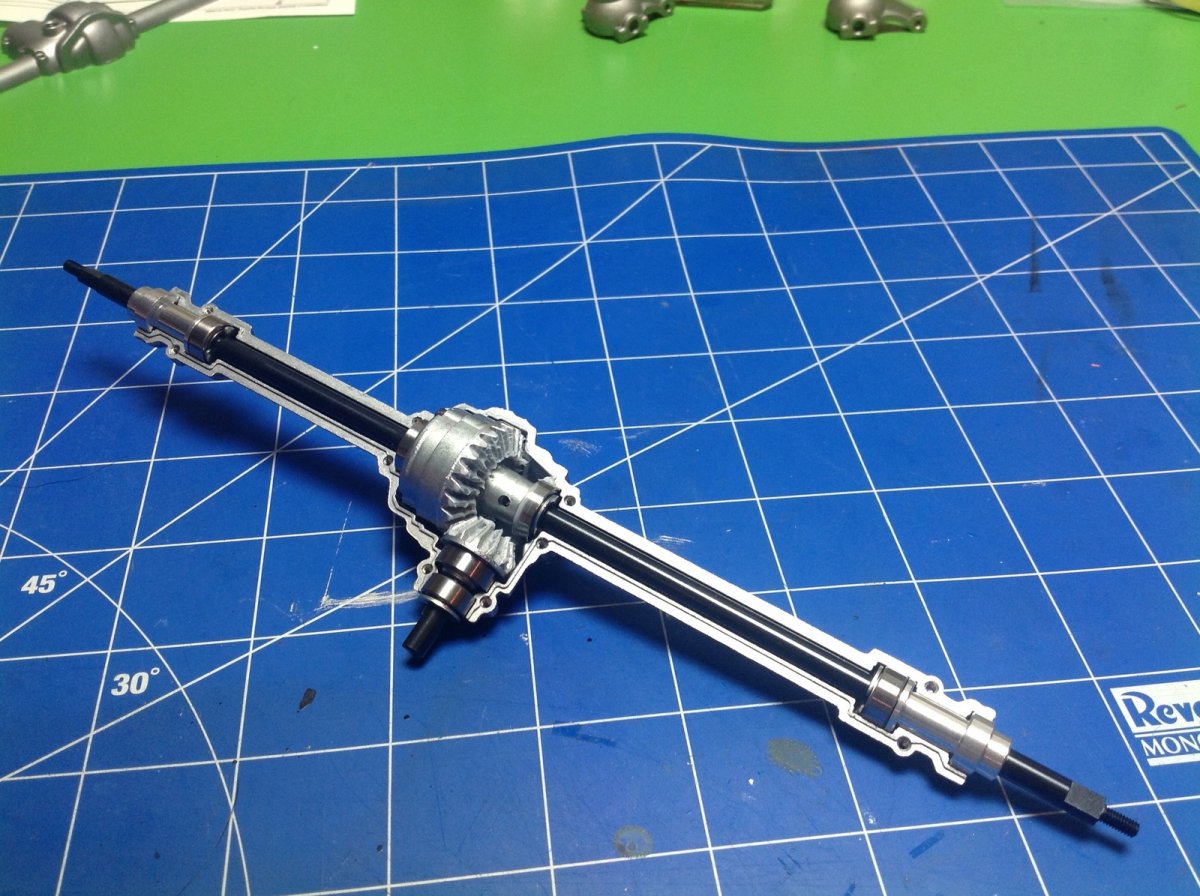
Time to build the differentials. Step 5 attaches bearings and stub axles to the 13 tooth metal pinion gears. The gears appear to be cast alloy rather than machined which makes them weaker than they could be but still stronger than plastic.
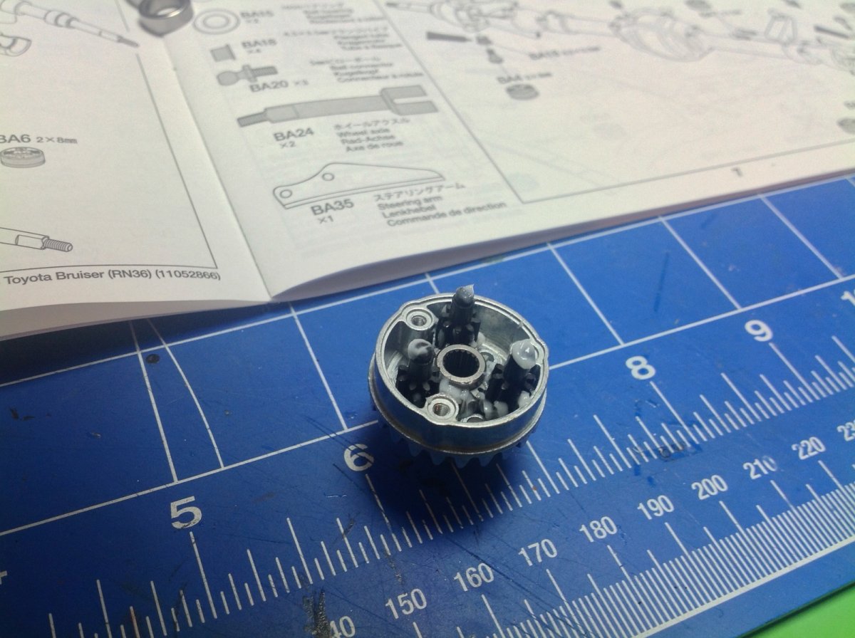
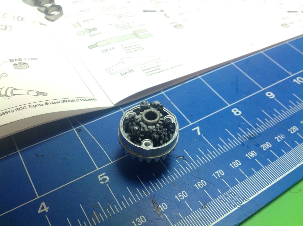
The model uses gear differentials, but not your standard bevel gear type. These are planetary differentials using only spur gears. The left picture shows the first layer which is an output sun mating with 3 planets. The planet axles are locked to the housing making it the planet carrier. The right hand picture shows the second layer which is another set of planets and the opposite side sun gear. The two layers of planet gears mesh together to rotate opposite directions.
The 24 tooth ring gears are integral to the housings. When the housing spins, the planet carriers follow along. As long as no wheels are slipping, the planets do not rotate. If one wheel slips, the orbit of the planets allows the sun gears, which output to the axles, to spin independently. Awesome system. The original Bruiser actually had no differentials at all, it just used locked spools. This is one of the two primary differences between the re-re and the original, the other being the gearbox.
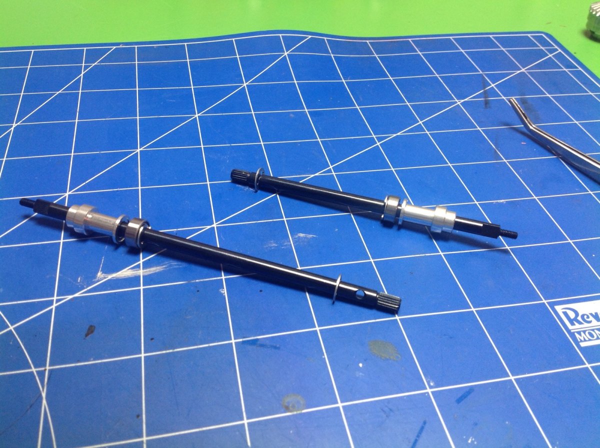
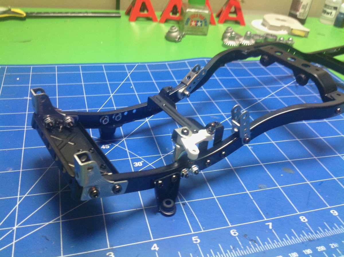
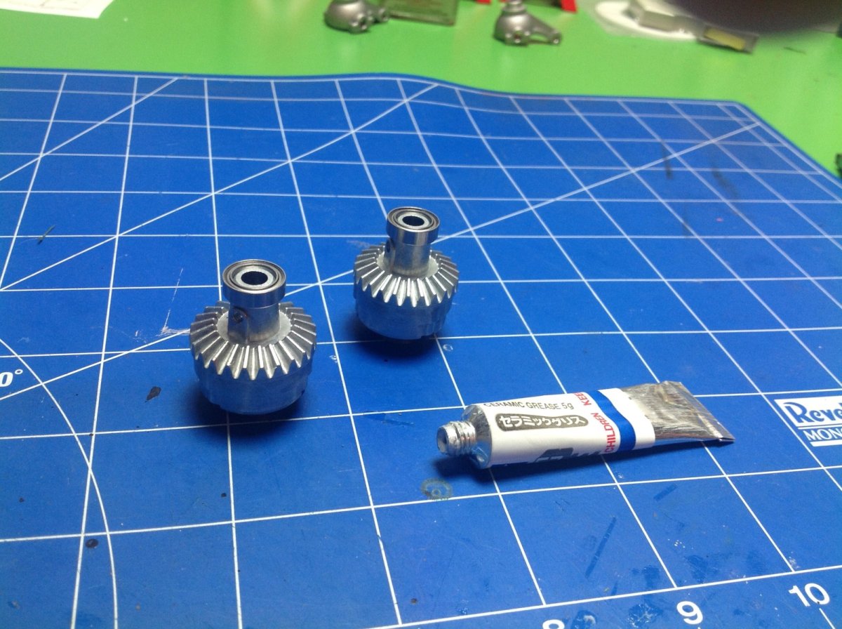
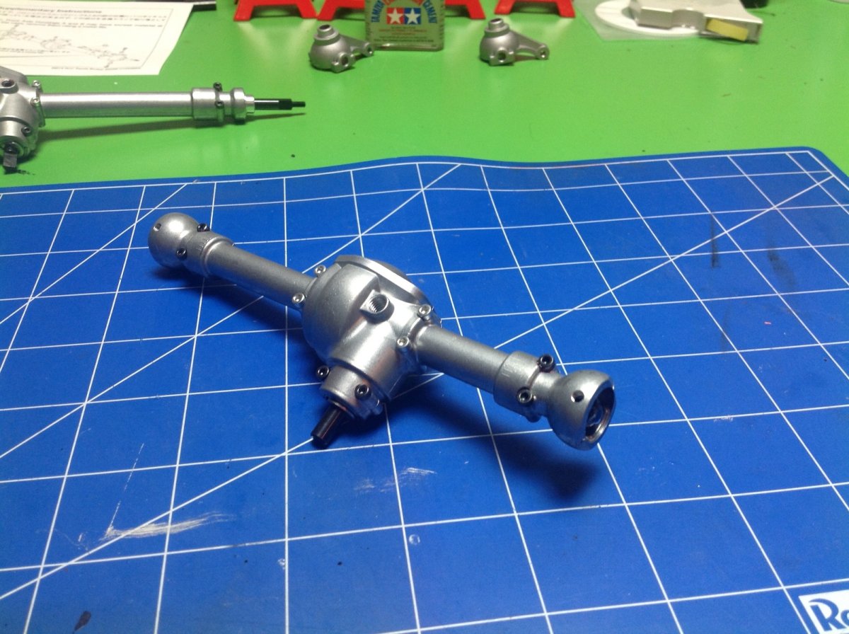
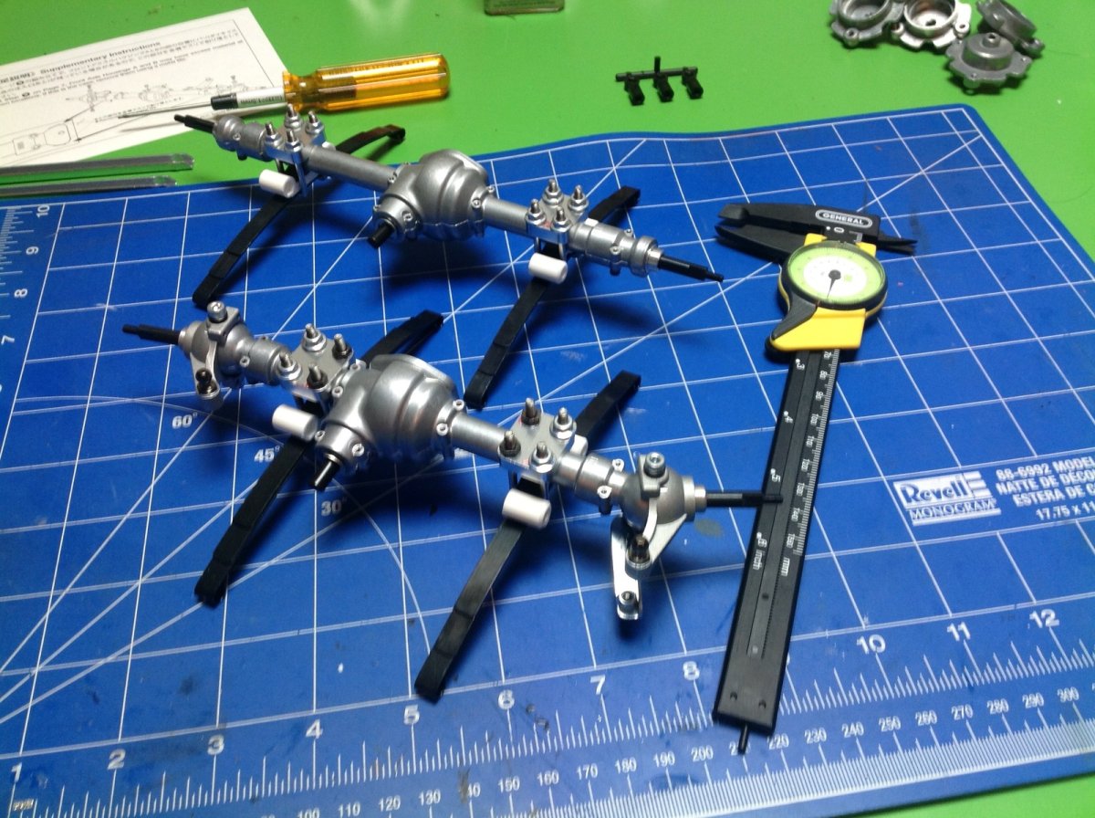
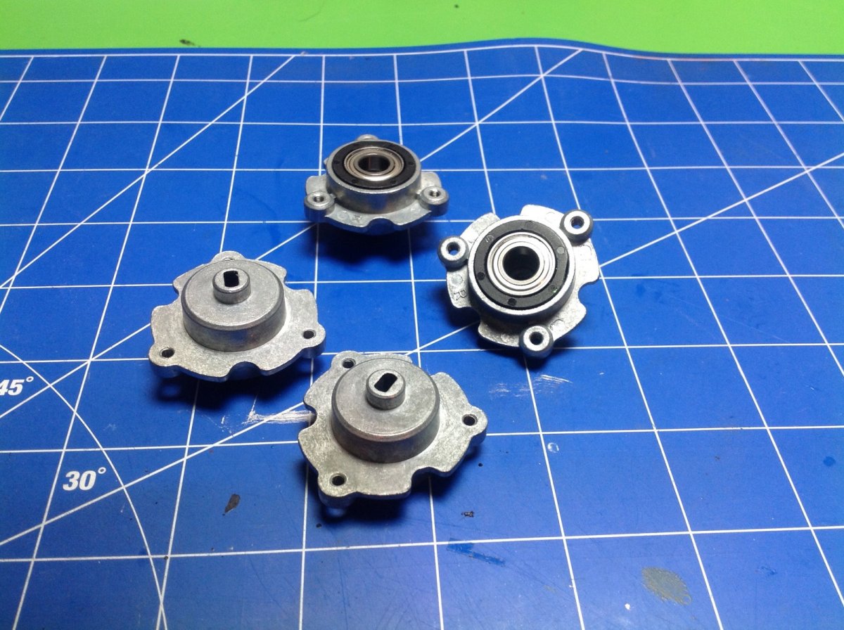
Now the rear axle. We start with a pair of splined steel shafts and add some aluminum support collars, ball bearings, and E-clips. The axle housing is cast aluminum as well and holds the axles, differential, and pinion. I was a little worried about how thin the wall of the axle housing is, but it has been no problem at all. Just make sure not to over tighten the screws.
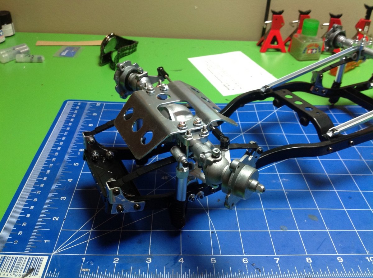
The front axle is a bit different because it has to steer. The basic construction of the internals is the same, but instead of ending in splined shafts the axles end in dog bones beneath a spherical hub. The second image shows the steering knuckles and output stub axles installed. In both images you can see an open hole above the differential. This is an access point to install a grub screw which locks the differential. It is really nice that you can lock and unlock the diffs, however this hole faces upward and is therefore not accessible once the axle assemblies are mounted, so it is best to decide now which way you want to go. I started by leaving the diffs unlocked but found once I finished that the off road traction was poor so I went back and locked them. Then I found that the steering was poor. As a compromise, I went back the third time and used Tamiya anti-wear grease to semi-lock them and I think that is the best choice.
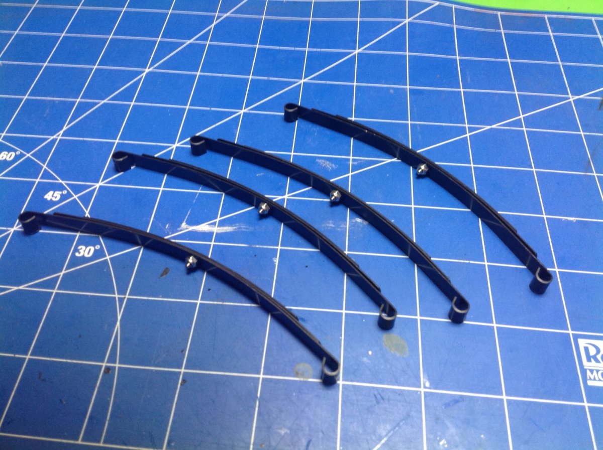
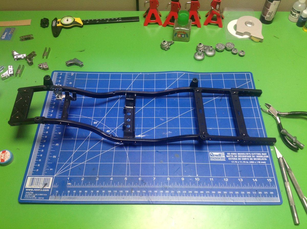
Step 10 opens hardware bag B and begins assembly of the suspension. We start with the leaf springs, each of which uses 3 stacked leaves. Nothing makes a better scale truck than real metal leaf springs. Next the springs are connected to the axles. This is actually a bit tricky because the axle housings can rotate in the saddle clamps until everything is tightened. You need to get them oriented correctly so the inputs will face the right direction to accept the drive shafts. The angles are shown in the instructions, but you have to eyeball them and then try to hold everything in place while you tighten. The manual says to use "synthetic rubber cement" here. I didn't know what that meant so I used CA which was a problem because then nothing can be adjusted. Turns out that you can use Shoe-Goo which I highly recommend. This will stay pliable so you can make adjustments. This step also adds only the second set of plastic parts which are the shock mounts. You can buy metal versions from RC4WD and if I were doing it again I would probably get them but they are difficult to retrofit because you have to do all the adjustments again. To be fair, I've had no problem with the plastic. Metal is just cooler. If you don't understand why then you shouldn't buy this kit.
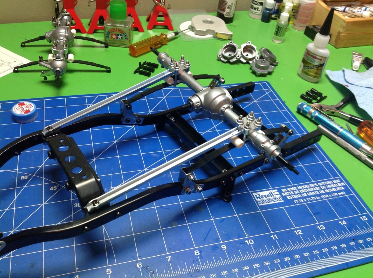
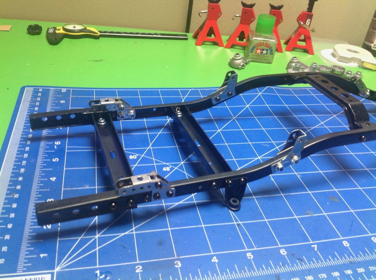
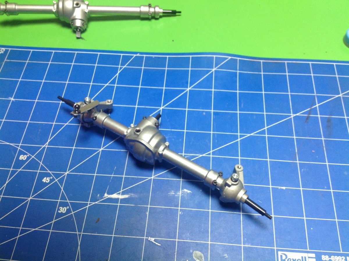
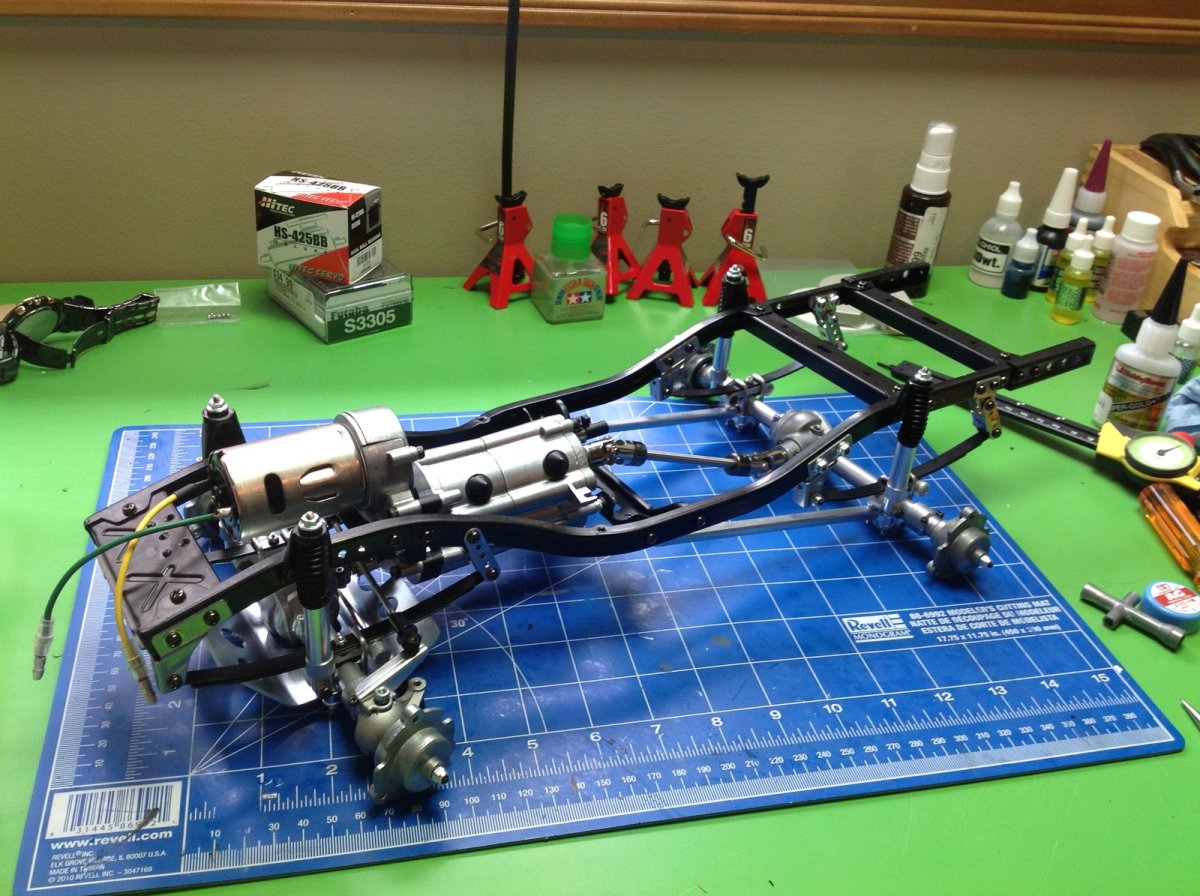
Now it is time to install the axles on the frame and make this look like a chassis. The rear suspension uses a pair of long trailing arms to stabilize the leaf springs and carry thrust loads. The front axle just bolts directly to the springs. There is no panhard rod, so steering forces get transmitted to the springs.
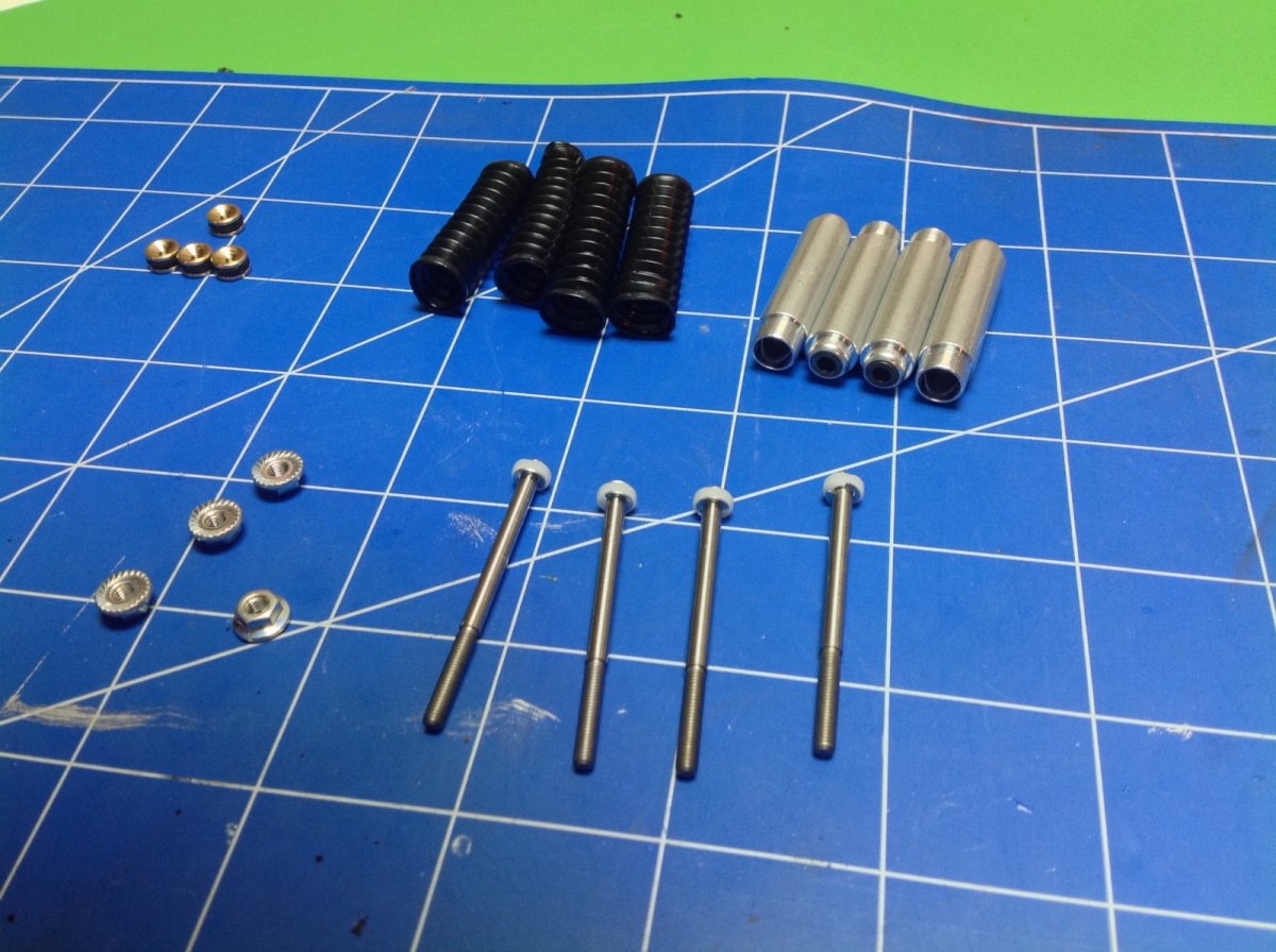
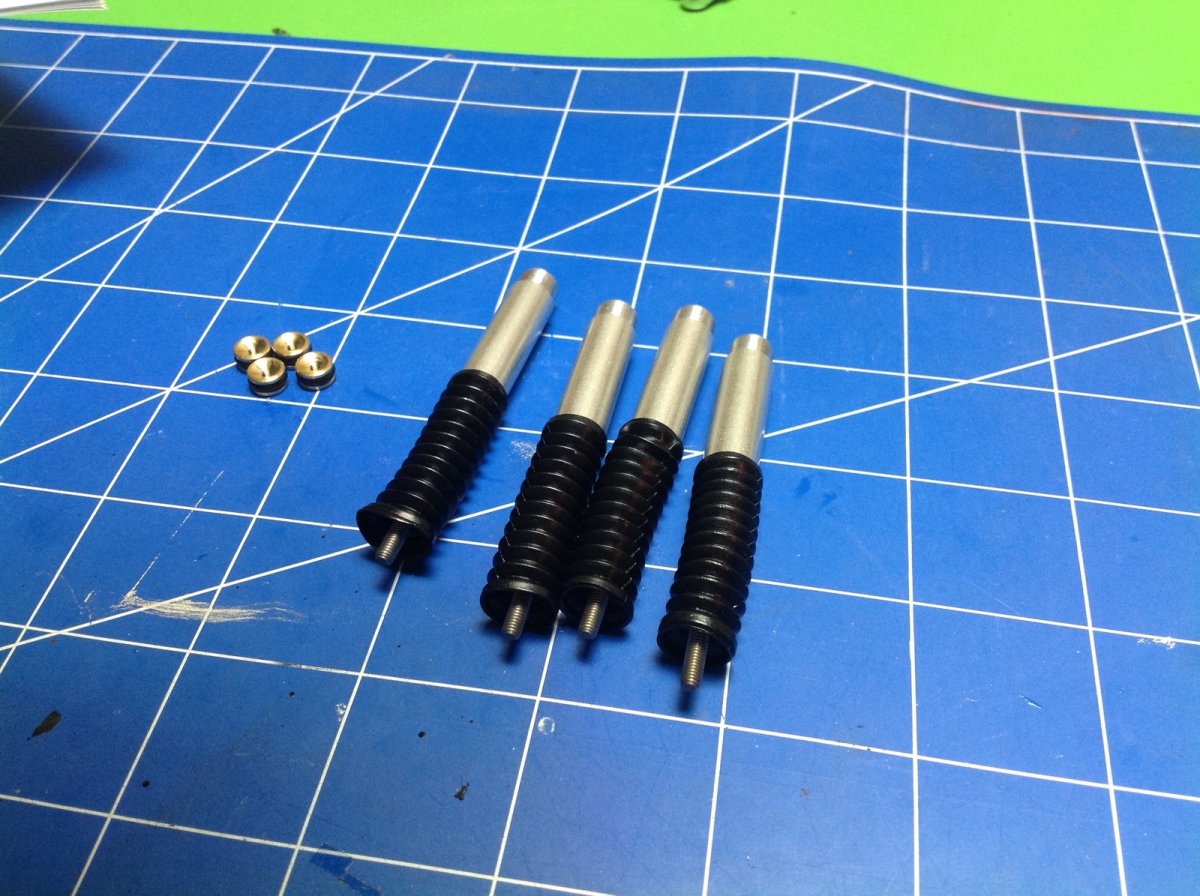
The shock absorbers are quite unusual. They are oil filled, but they are not sprung. They act only as dampers for the leaf springs. The main piston does not have any holes in it, instead is has flat spots on the side to allow for fluid passage. The piston is retained with E-clips. After filling the shock, you add a second floating piston which has an o-ring seal. This replaces a bladder for volume compensation and floats up and down with shock stroke. There's a nice rubber boot which protects the main rod seals from contamination.
Once the head ends are installed the shocks are complete. There are no rod ends. The rod threads directly into the damper stays on the chassis.
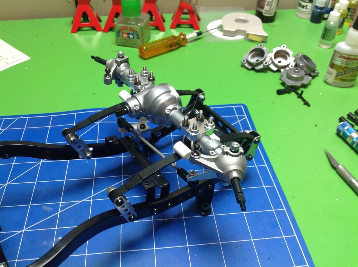
Step 15 builds the highly unusual wheel hubs. No hexes here. The stub axles have flats which drive the hubs, and the wheels actually bolt onto the hubs with 3 screws.
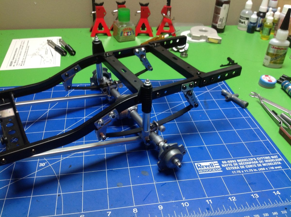
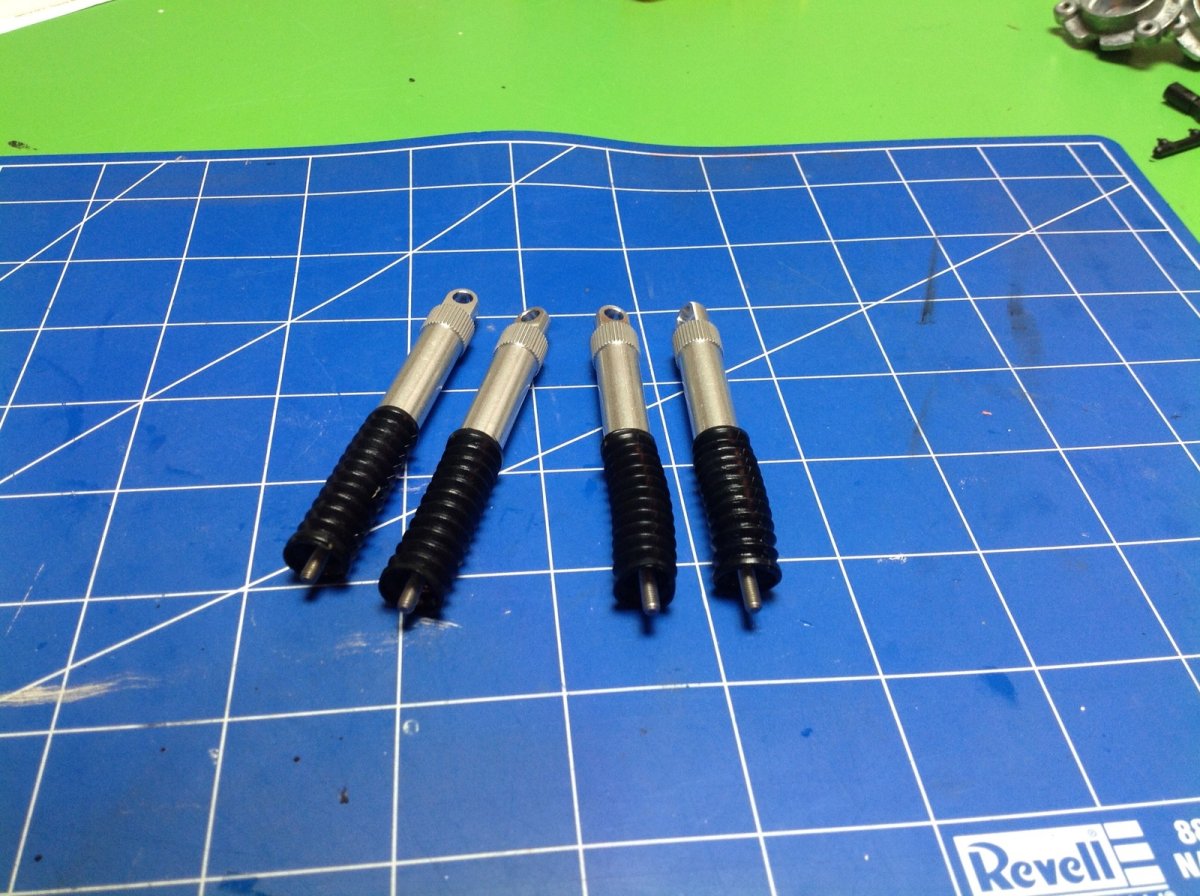
Now the dampers and wheel hubs are added to the chassis. Note the unusual inverted damper arrangement and the lack of rod ends. The left image shows the rear axle and the right image shows the front with protective skid plate.
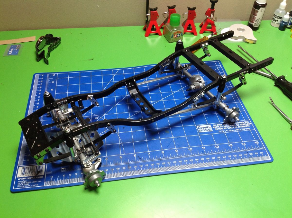
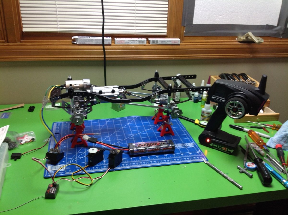
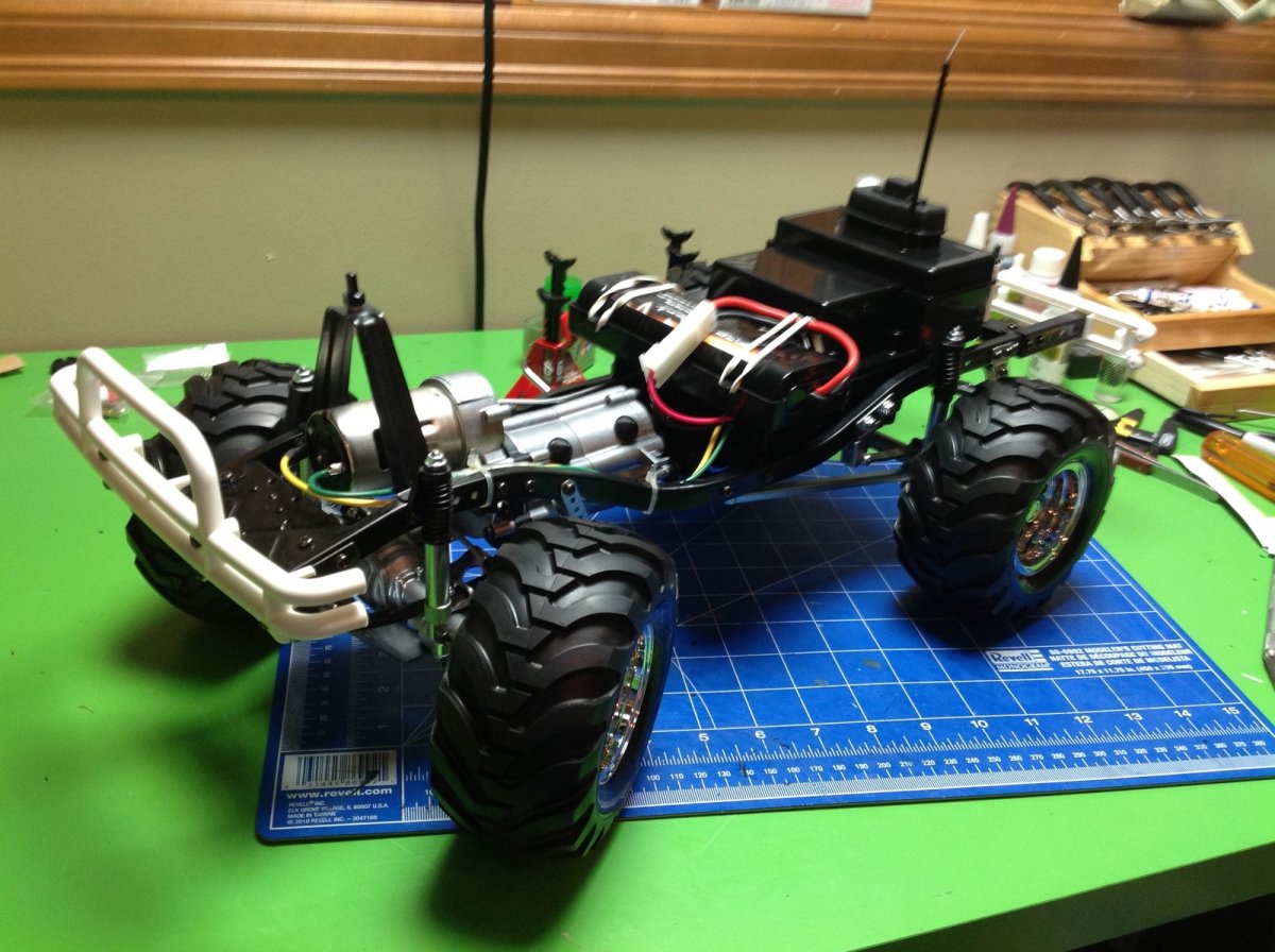
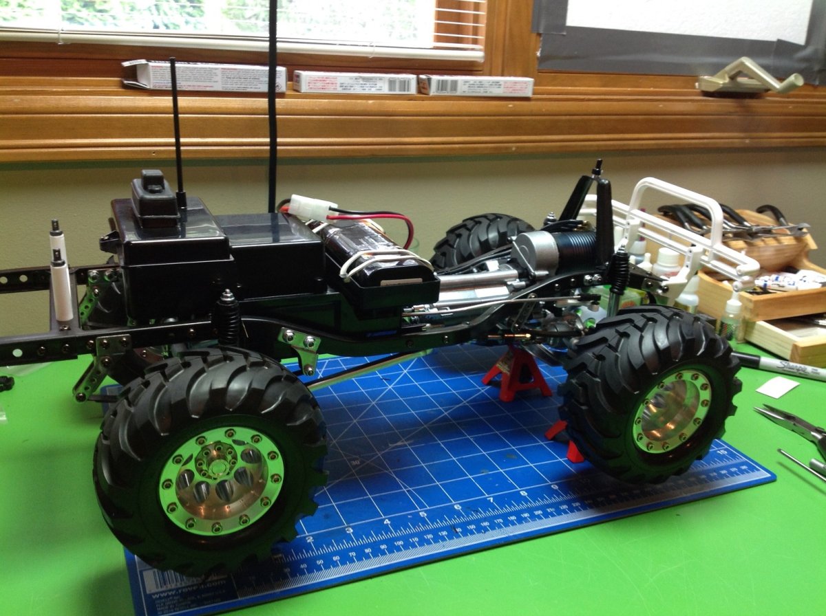
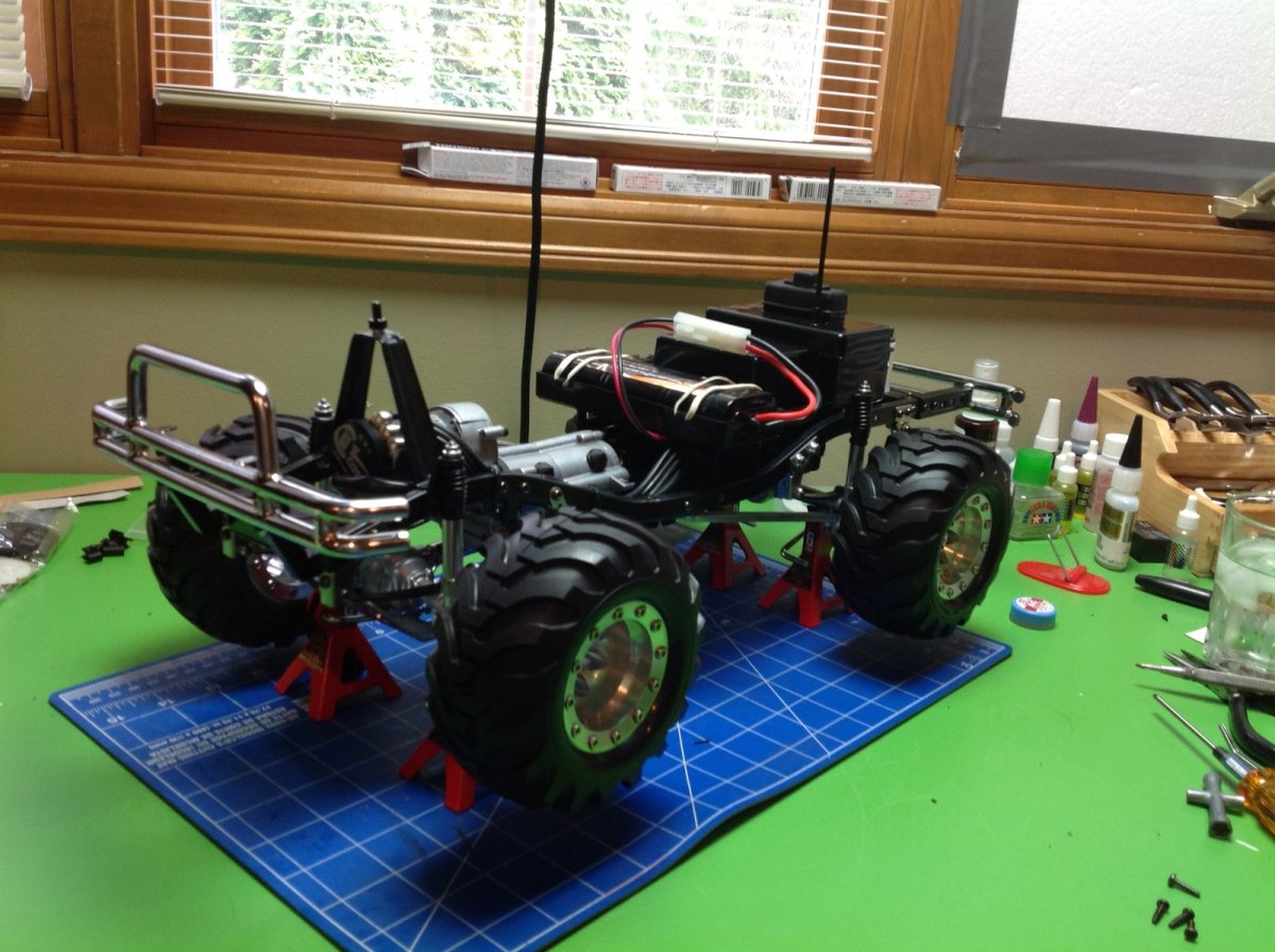
After Step 17 the rolling chassis is complete. Pretty much everything you see here is metal and it is glorious. There are no weak links here, you can grab it anywhere and shake it around and everything stays well together.
Building the Transmission
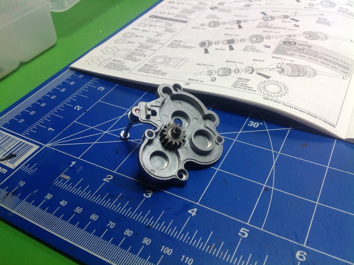
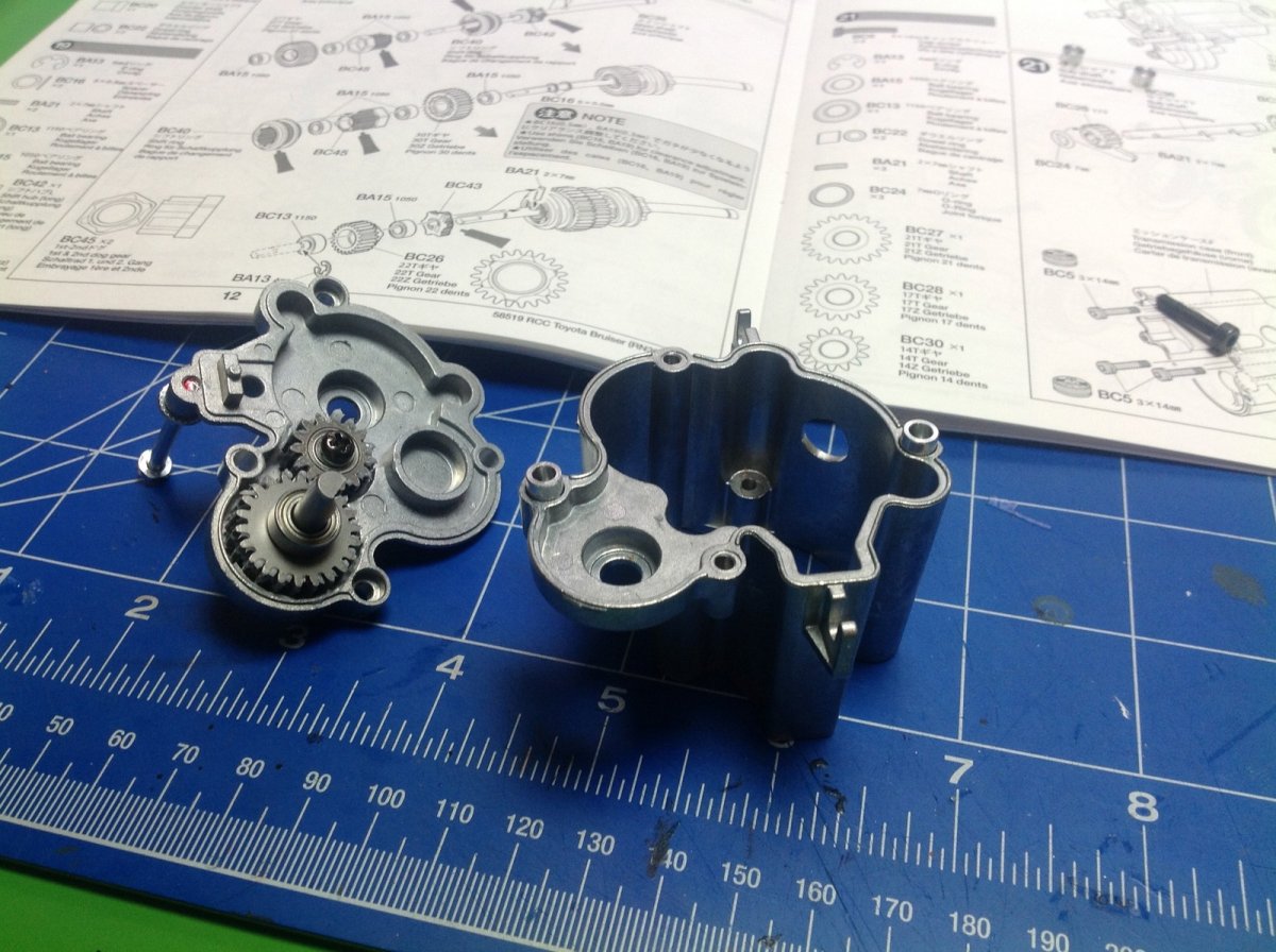
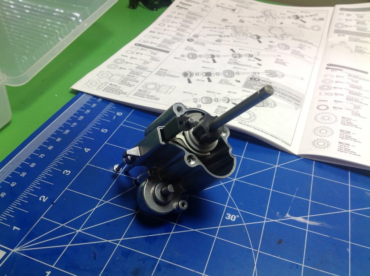
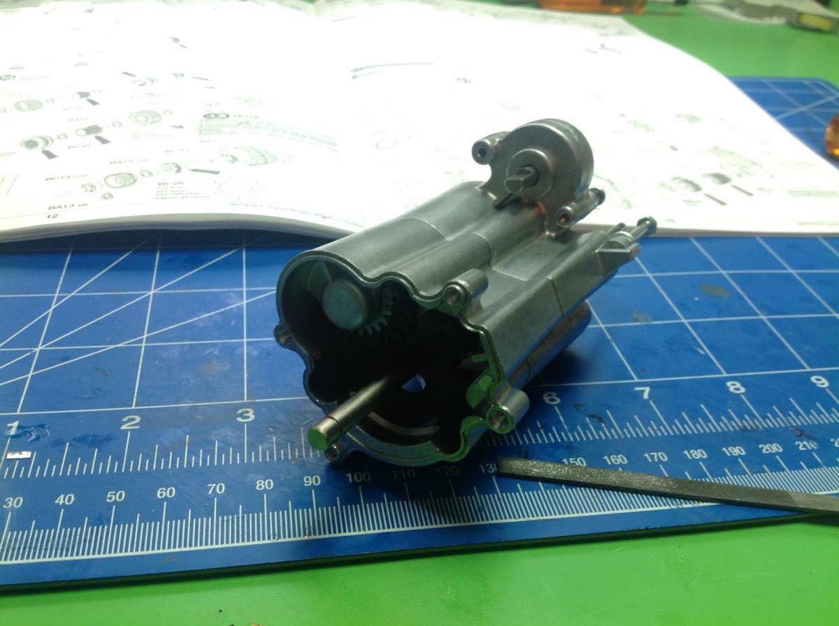
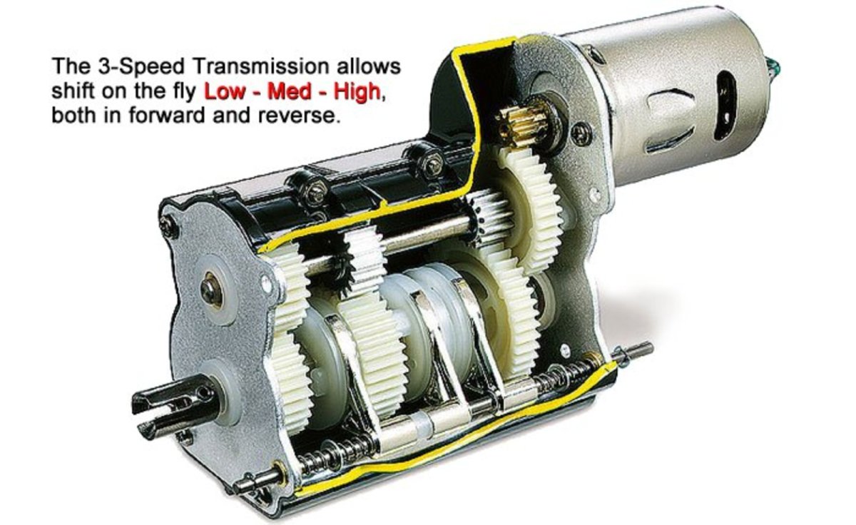
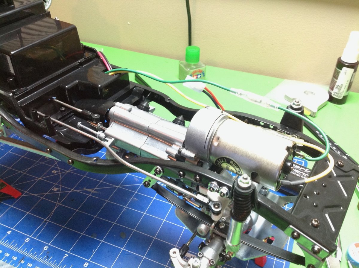
The 3-speed transmission is a thing of great beauty. I expected that it would be pretty much the same as the 3-speed in the King Hauler (or other tractor trucks, or Highlift trucks which use essentially the same transmission), but that's not true at all. This is a completely unique beast, and actually much more complicated than the King Hauler. The housings are cast aluminum, and the build starts in Step 18 with the installation of a pair of spur gears rolling on bearings. The screw protruding from the end cap is used to support the transmission. The two gears in the second image are not part of the system to change gear ratios, but rather drive the transfer case. This transmission is only four wheel drive in first gear, so these gears are connected to the lowest gear on the main shaft.
Once the first two housing sections are bolted together, the transmission looks like this.
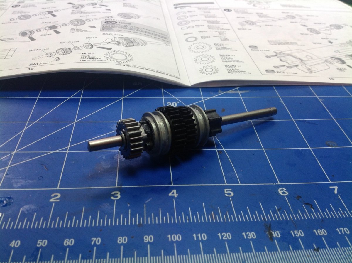
Next comes the build of the main shaft. The parts shown in the left hand image are the driving rings. The darker parts are keyed to the shaft. The lighter aluminum collars slide along the drive rings and engage floating gears. The right hand image shows the completed main shaft. There are 3 gears: a 30 tooth, a 27 tooth, and a 22 tooth. Each floats on bearings and does not engage the shaft unless the collars grab them. The 22 tooth gear drives the transfer case and does not control ratio changes.
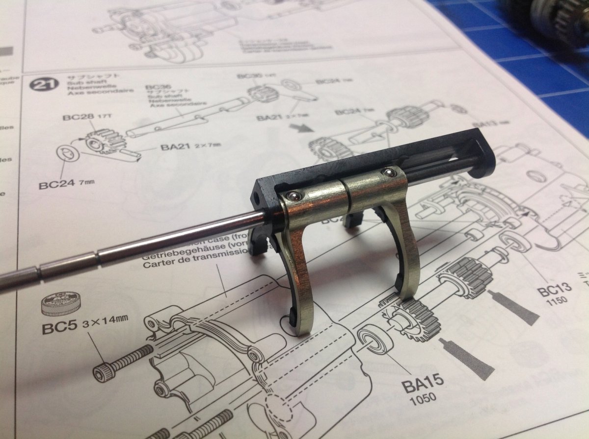
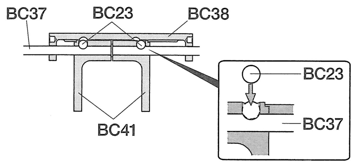
The shift forks contain the magic. You can't simply translate both shift forks at the same time. This would engage multiple gears and jam the transmission. You would expect to need 3 shift forks for a 3-speed, so how do you do it with only 2? The answer is the little raceway for the balls that drive the shift forks. The C-shaped dark part in the left hand image contains the raceway. Each shift fork has a hole for a ball. When the balls are in a raceway detent they can stand proud of the forks which then slide along the axle (which is driven by a servo) When the raceway drives a ball into a detent in the rod, the fork is pushed to follow the rod. It is really hard to describe and just as hard to figure out even when you have the parts right in front of you, so the picture on the right might help. This is an excerpt from Step 20 of the manual which shows the balls, the forks, the rod, and the raceway.
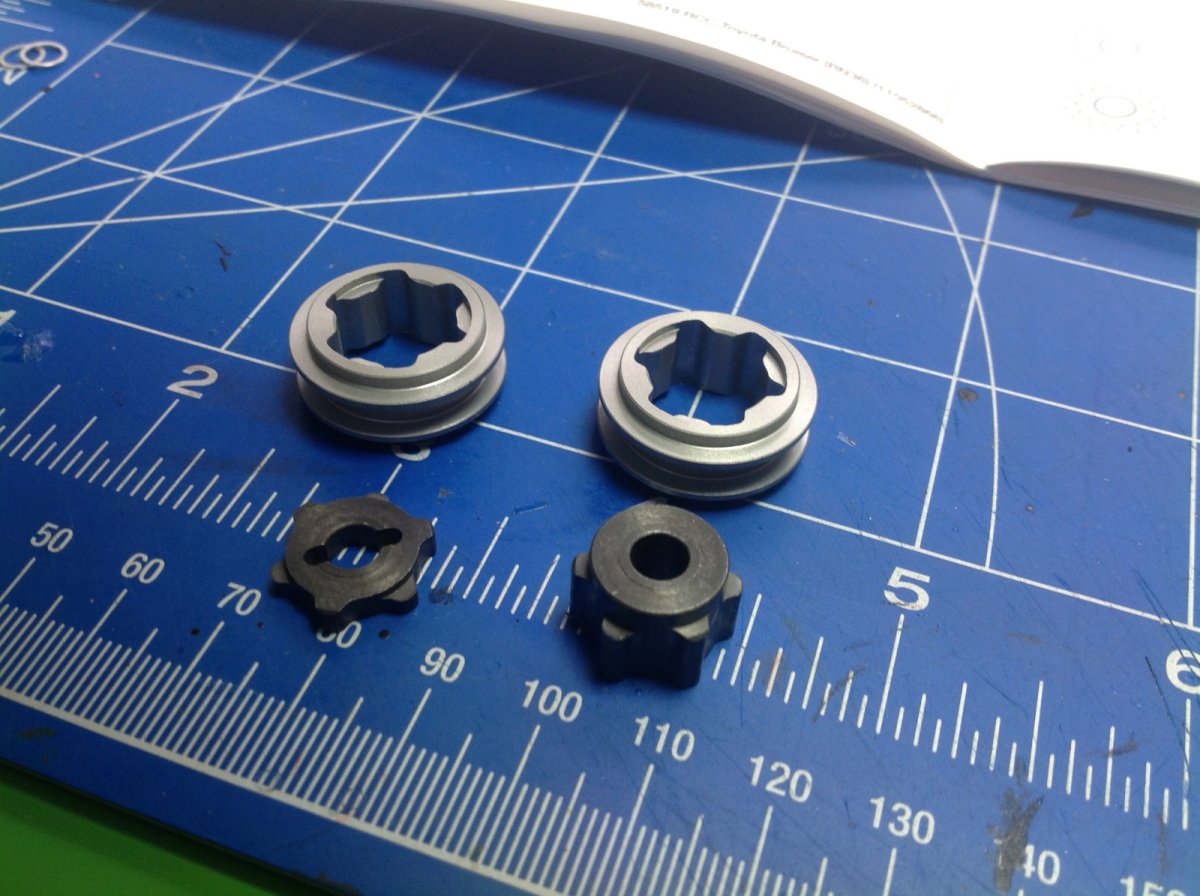
Note the plastic "shoes" on the shift forks which help to minimize friction as the driving rings rotate beneath them. The kit comes with extras for when these wear out.
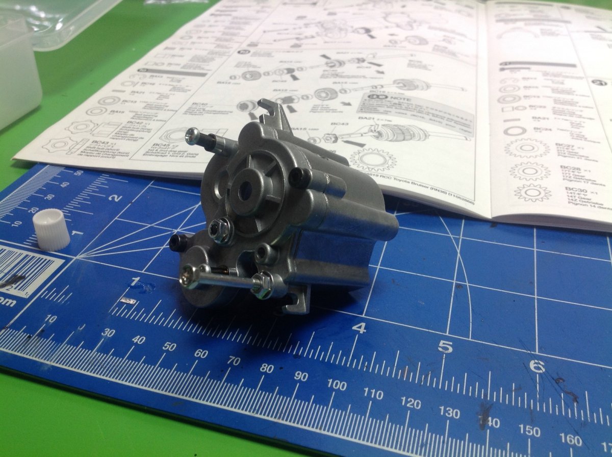
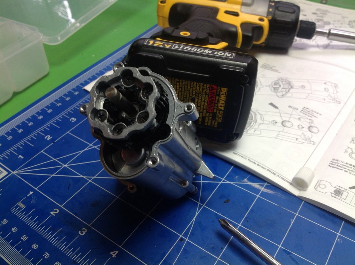
Now the shift rod assembly needs to be mated to the main shaft and the pair needs to be carefully inserted into the housing. There is a rectangular support for the raceway which keeps it aligned with the shift rod.
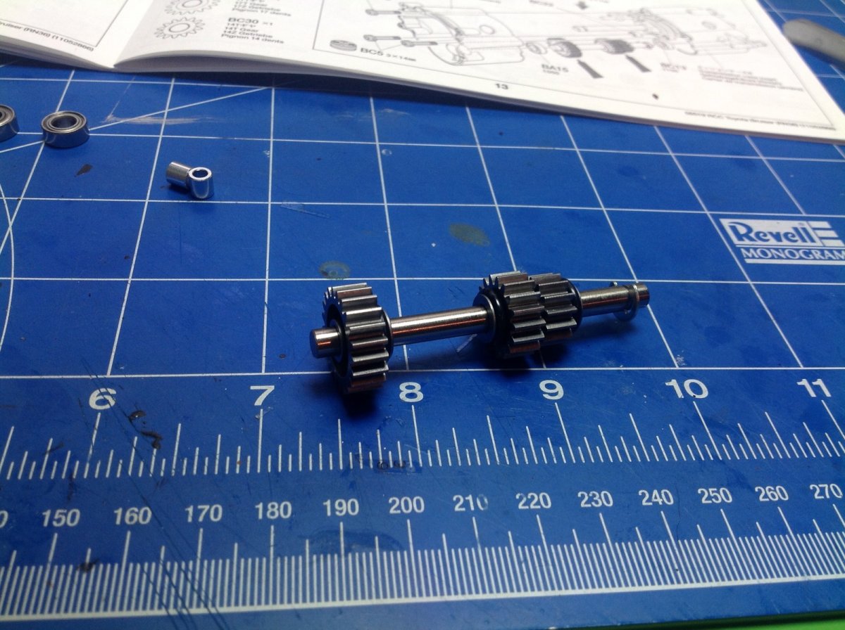
Next is the secondary shaft. Like the main shaft this has 3 gears on it, but unlike the main shaft these are all locked to the axle. We have 14 teeth, 17 teeth, and 21 teeth here. All three gears control ratio changes, but the largest does not mate with anything on the main shaft. It's mating gear comes in Step 22 below.
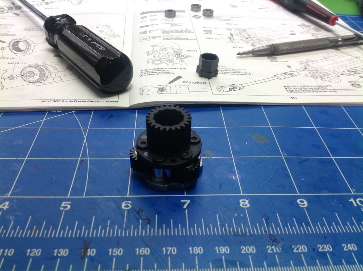
The first stage of the gearbox is this planetary system. The big output gear is connected to the planet carrier and has 23 teeth. Each of the 3 planet gears has 20 teeth. The planetary assembly is inserted into the gearbox housing where the 23 tooth output gear mates with the last gear of the secondary shaft.
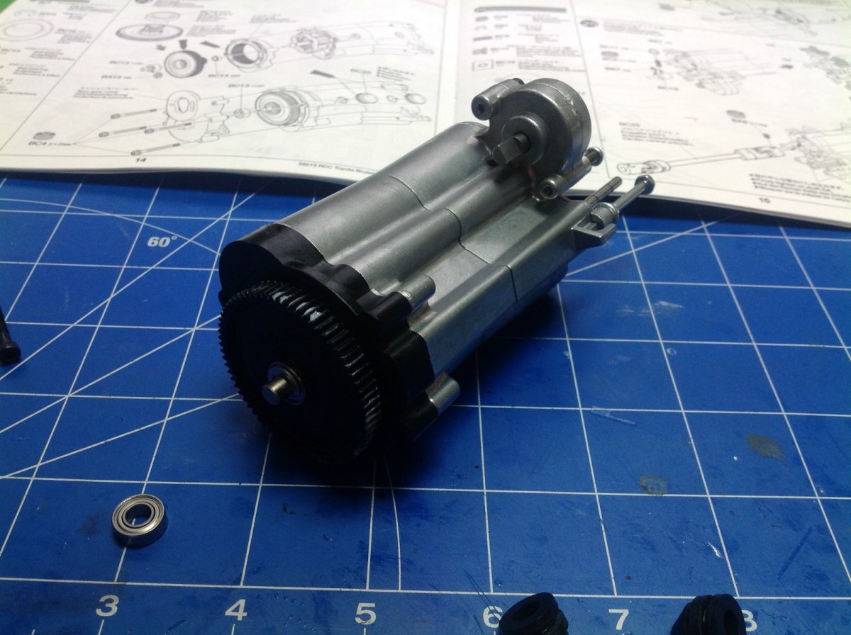
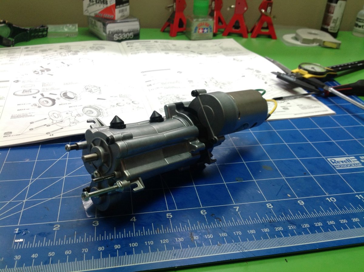
In case it wasn't complicated enough yet, now we get to add a plastic 59 tooth ring gear to mate with the orbiting planets. The 70 tooth spur gear has an integral 19 tooth sun gear for driving the planets. The final step in building the transmission is to attach the motor and 19 tooth pinion. Phew!
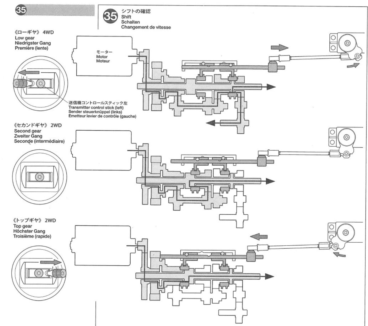
This path through this gearbox is about as convoluted as they come, but luckily Step 35 in the manual is not a step at all but an explanation of the torque path through the gearbox, shown above (click for a larger version). With this assistance of this picture, we should be able to derive all the final gear ratios. Let's break the problem into parts:
- Motor Ratio = 70:19 = 3.684:1
- Planetary Ratio = 1+(59/19) = 4.105:1
- 1st Gear = 21:23 x 30:14 = 1.957:1
- 2nd Gear = 21:23 x 27:17 = 1.450:1
- 3rd Gear = 1:1 (Note that 3rd gear goes straight through and doesn't use the secondary shaft at all)
- Transfer Case = 22:15:22 = 1:1
- Differential = 24:13 = 1.846:1
Therefore final drives are:
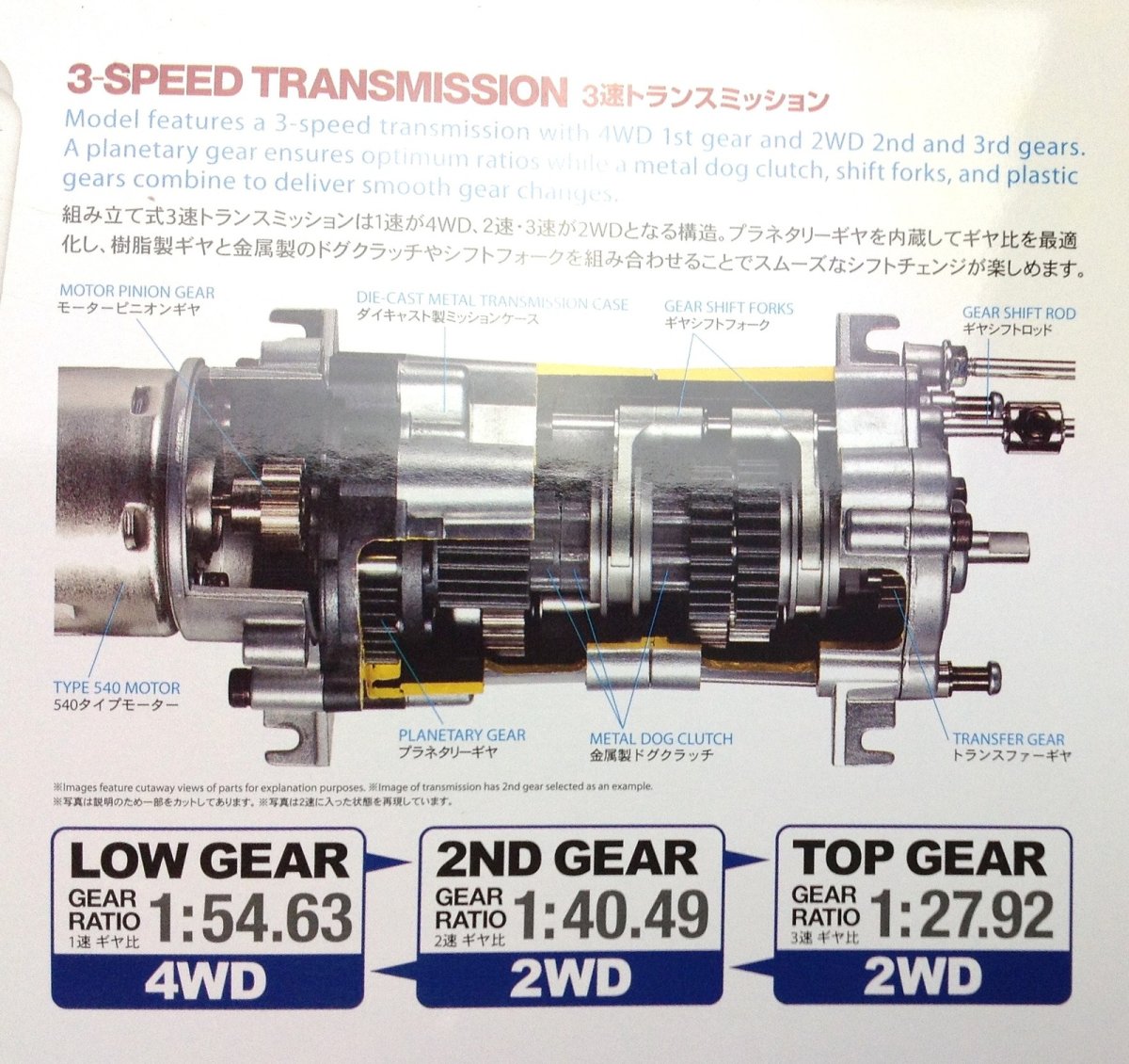
- 1st Gear = 3.684 x 4.105 x 1.957 x 1.846 = 54.6:1
- 2nd Gear = 3.684 x 4.105 x 1.450 x 1.846 = 40.5:1
- 3rd Gear = 3.684 x 4.105 x 1 x 1.846 = 27.9:1
I am happy to report that I did this entire exercise without first looking at the picture on the box and I got the same answers!
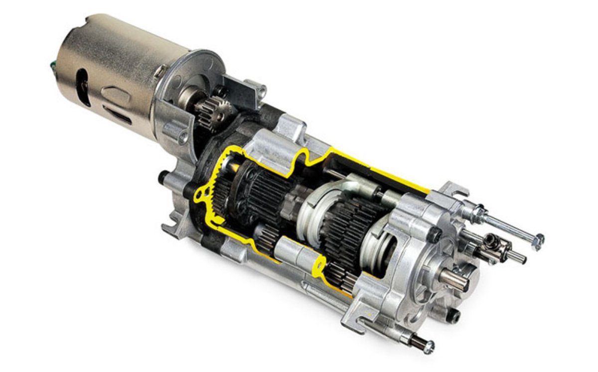
If we compare the 3-speed transmission in the Bruiser with the 3-speed transmission in a 1/14th scale tractor truck or Highlift truck, we can see the significant differences. They both have two axles, but the Bruiser has 2 shift forks while the tractor has 3. The tractor transmission uses driving dogs which make it easy to shift gears at any speed. The Bruiser driving rings need to be synchronized to allow the lobes to slip into place, so sometimes it takes a moment to shift or even refuses until the right RPM is reached. The Bruiser has the additional function of engaging the transfer case in first gear and freewheeling in other gears. Finally, only the Bruiser has the cool planetary reduction. With all this extra complexity probably comes less reliability, but so far I have had no problems with either. The Bruiser version is quite a challenge to build and get right though. It took me a couple of tries to get everything lined up correctly .
Just for fun we can look back at the original Bruiser transmission from 1983 and see that it is significantly different. Besides using a 750 sized motor, is also lacks the planetary reduction and uses 3 shift forks.
Finishing the Chassis
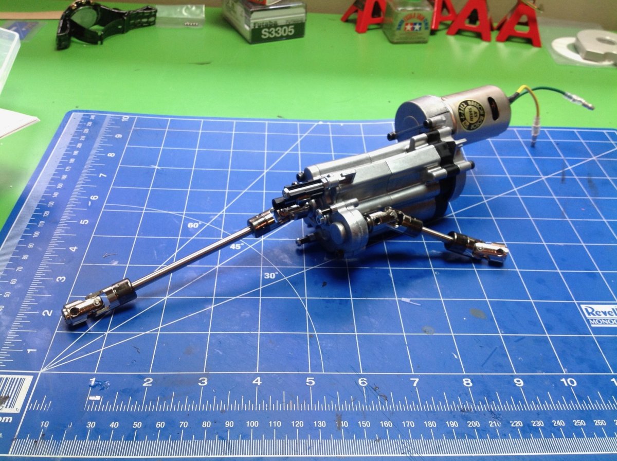
Step 25 installs the drive shafts onto the gearbox. The drive shaft and u-joints are really nice steel units which allow a bit of telescopic motion. The instructions tell you to put some CA glue on the E-clips of the u-joints but I ignored this advice and paid the price later when one fell off. Follow the instructions.
Step 26 installs the gearbox in the chassis. The mounting system is very clever. The whole assembly just slips into a pair of rubber grommets which act as vibration isolators. This makes it fairly easy to remove. At this point, nothing is stopping us from hooking up the electronics and firing up the motor, so of course that's what I did. At this point the transmission is locked in 2nd gear, but you can actually drive around on the wheel hubs to try it out.
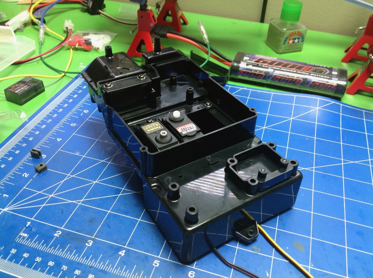
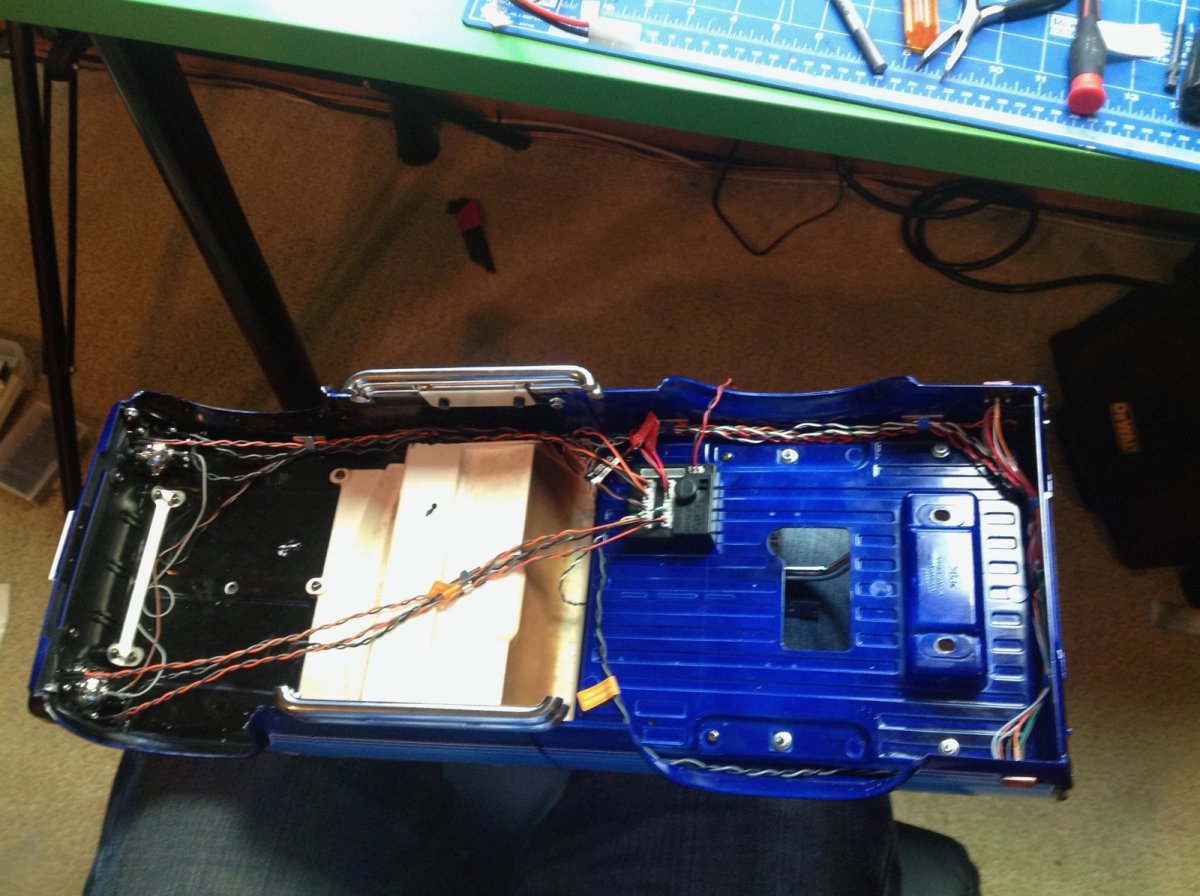
Steps 27 and 28 have you test wire the electronics. I started out with a Tamiya TEU-105BK controller and a 5000mAh NiMH battery along with a Spektrum 3 channel receiver. Step 29 installs the servos into the electronics box. I used a Futaba S3305 for steering because it has good torque but a cheap HiTec HS-425BB was good enough for shifting. The original would have had a 3rd throttle servo to control the mechanical speed controller. The servos face downward when installed on the chassis. The electronics box does a reasonably good job of protecting everything from contamination or water, but is not completely sealed.
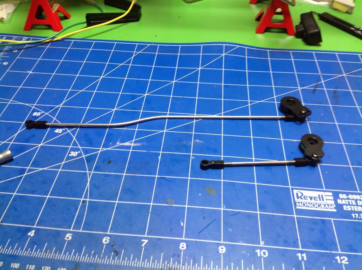
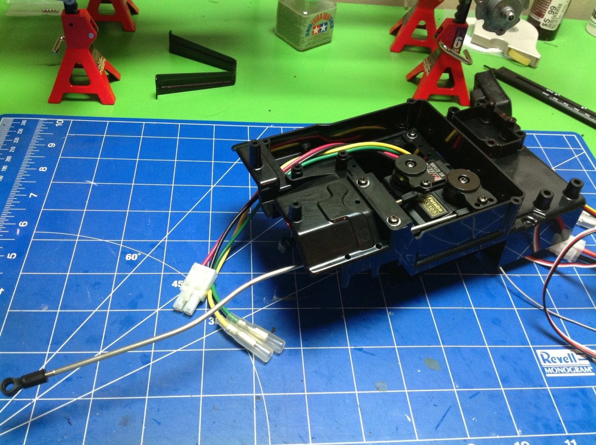
Because the electronics box is located on the back of the chassis, we need long linkages to reach the steering and shifting balls. The kit comes with two high torque servo savers which use metal springs. The rods exit the electronics box through an opening which is sealed with a rubber flap.
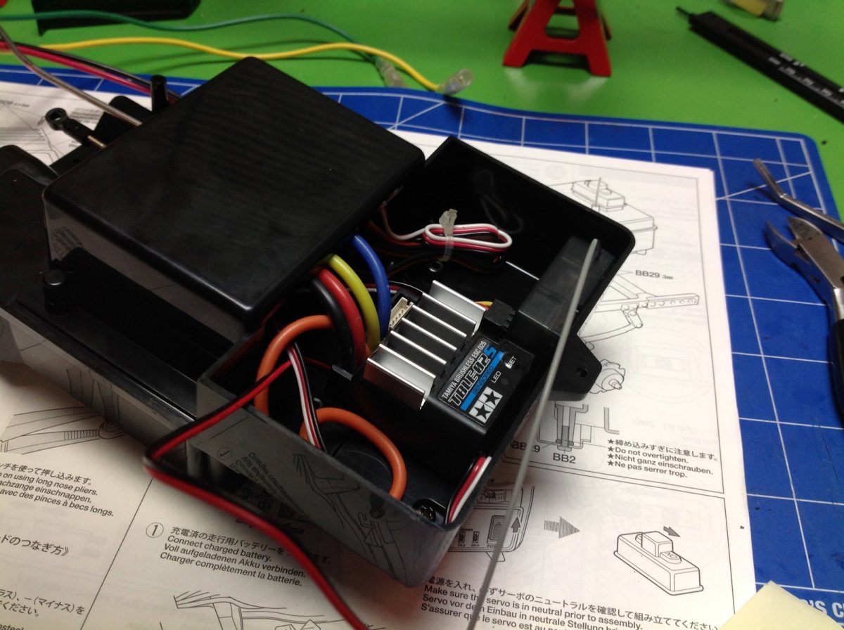
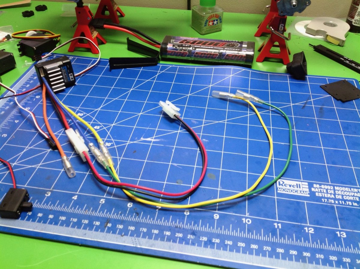
Now we flip the electronics box over and install the ESC, the receiver, and the power switch. Because the box is so far back, both the battery wire and the motor wires need extensions which are included with the kit.
Now the electronics box is installed in the chassis and the wires are connected. Some of the screws and washers are a little tricky to get to here. Once installed, we can hook up the other end of the ball end links for steering and shifting. Now is also a good time to adjust the lengths and make sure the steering is straight at neutral and the 3 shift positions work. I highly recommend using a programmable radio which allows assigning a switch for shifting and adjusting the end points. This is much easier than using a 2-stick radio with shifting on the left stick as the instructions recommend.
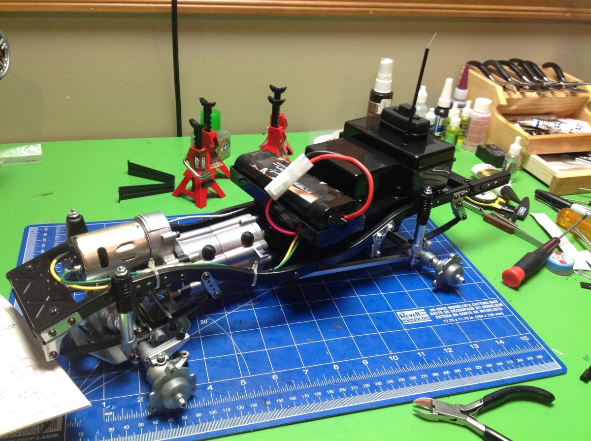
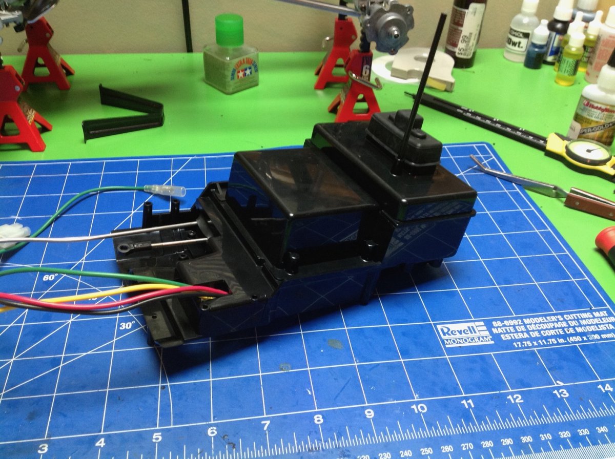
Next the tray for the battery is installed. The battery sits in the tray and is held with rubber bands. Then the white plastic bumpers are installed as well as the triangular body support above the motor. The original Bruiser had a different battery tray that was sized for the larger 6V pack available at the time. This tray is from the Mountaineer.
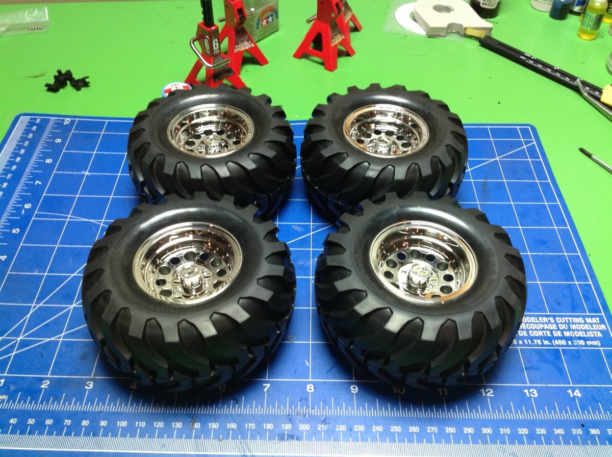
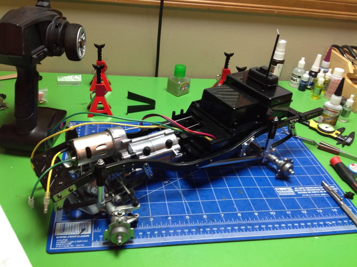
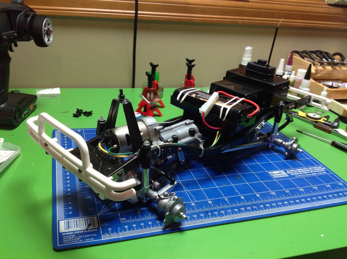
The final step in getting this thing rolling is installing the wheels and tires. There is really no reason to glue the tires, and the instructions do not tell you to do so. The tread is directional though, so make sure you get it facing the right way on each side of the vehicle. The tires are quite stiff and there are no foams. The original Bruiser actually used beadlock wheels, not one piece wheels like these. The later Mountaineer used these wheels though.
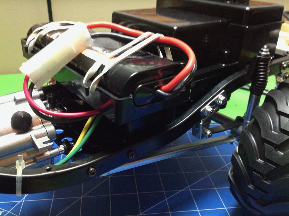
One modification I made immediately was to use a Dremel to enlarge the end of the battery tray slightly to allow the use of longer batteries. This made my standard packs fit much better. LiPo batteries tend to be even longer, but they honestly don't offer much advantage on a model like this.
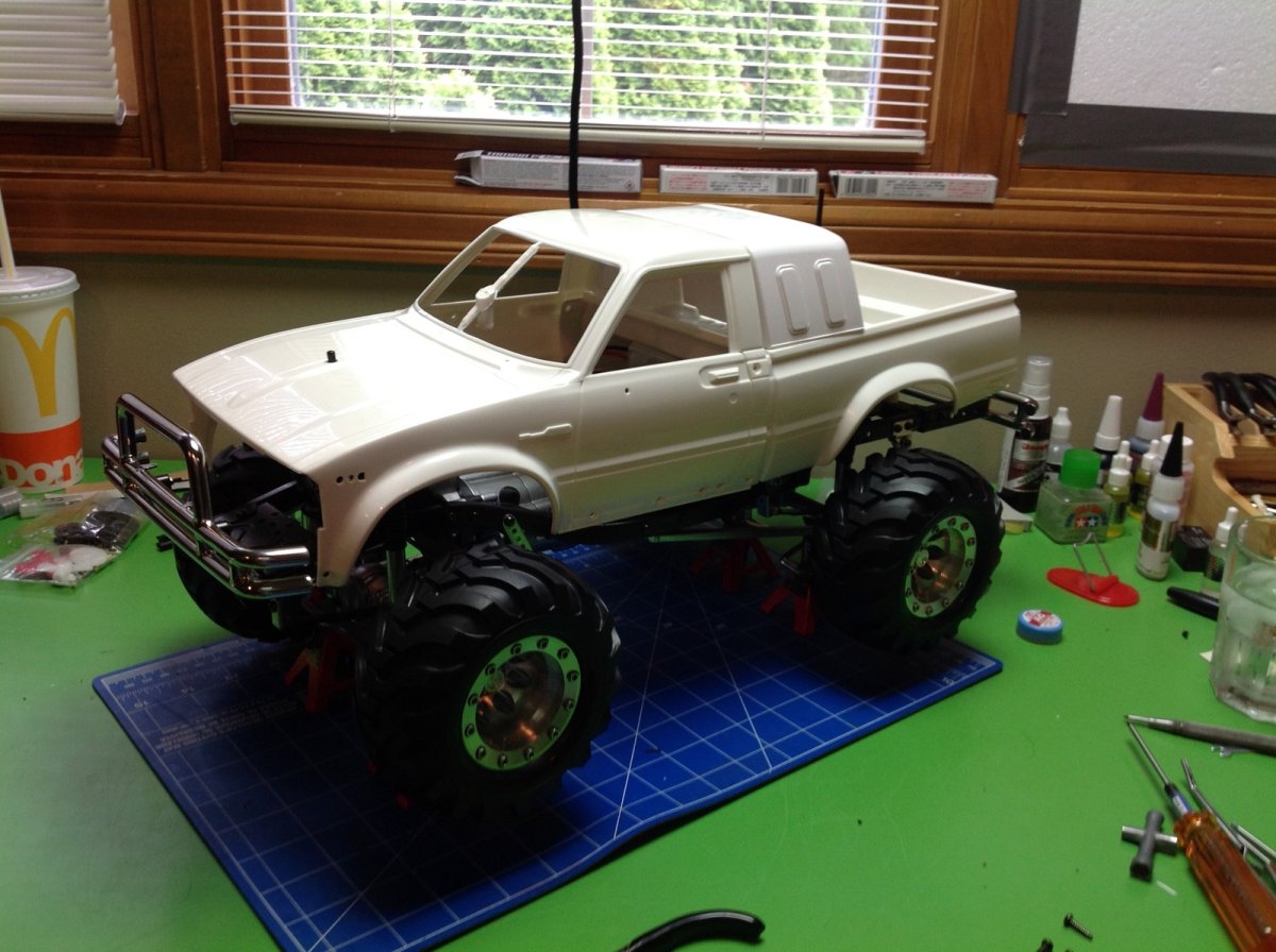
At this point it seemed only reasonable to dry fit the hard shell body onto the chassis to see how it looks. It looks real good!
Building the Body
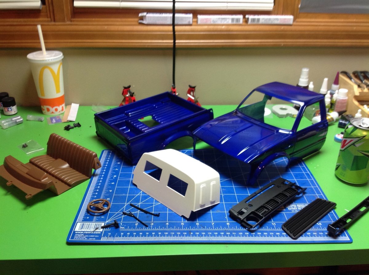
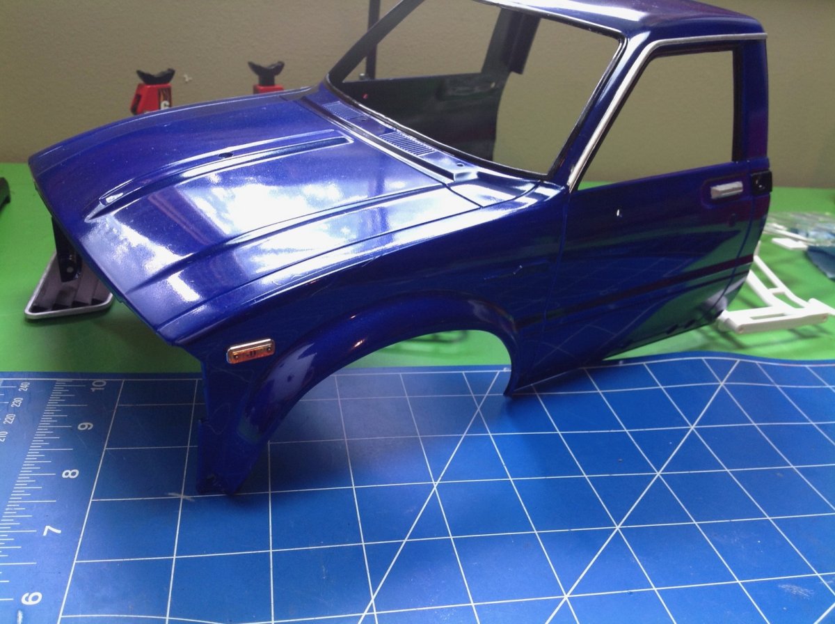
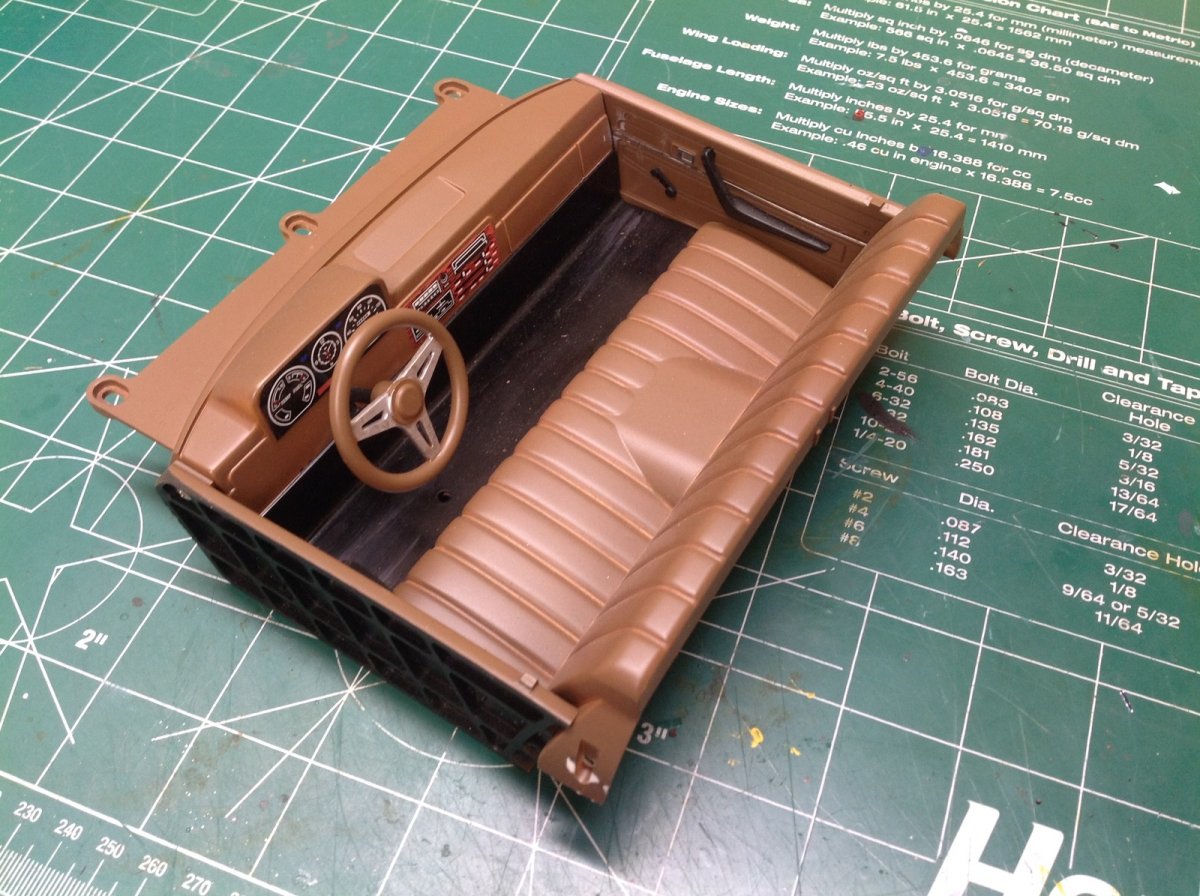
The body consists of two primary pieces: the cabin and the bed. But there are also several other large parts including the sleeper, the seats, and the grille. All the main parts come molded in white so everything needed to be painted. The instructions call for TS-15 Blue, but I used TS-53 Deep Metallic Blue instead. The sleeper is TS-7 Racing White, and the interior is TS-1 Red Brown. All of the black bits are TS-29 Semi Gloss Black. At this point everything has just been sprayed.
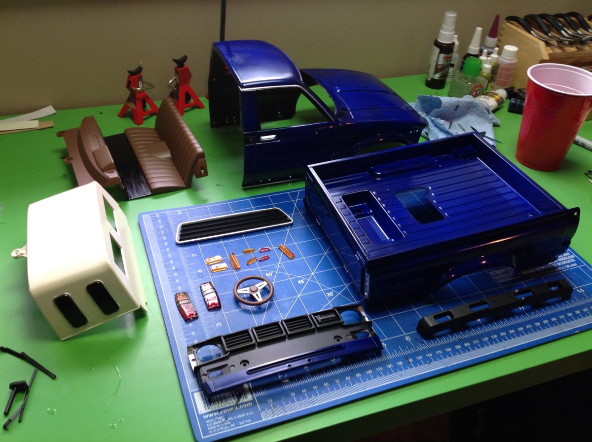
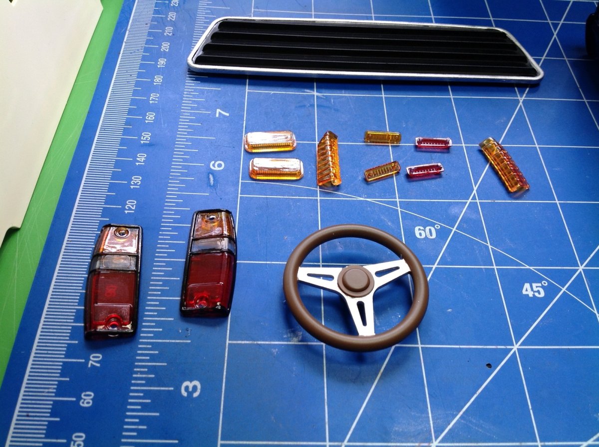
Time for some more detail painting. The sleeper needs black windows and the interior needs a black floor. Silver trim is needed around all the windows, behind the marker lights, and on the door handles. All of the lenses came in transparent clear, so trans red and trans orange were needed to tint them. You can see the fine detail work that was needed on the tail light lenses in particular. All of this was done with a fine brush. When I was done with the detail work, I also painted the entirety of the inside of the body black. Since some of the underside may be visible when the body is mounted, I wanted it to blend into the chassis. It worked well, but took a whole bottle of black paint. I did it with a brush because I couldn't think of a good way to mask it for spraying.
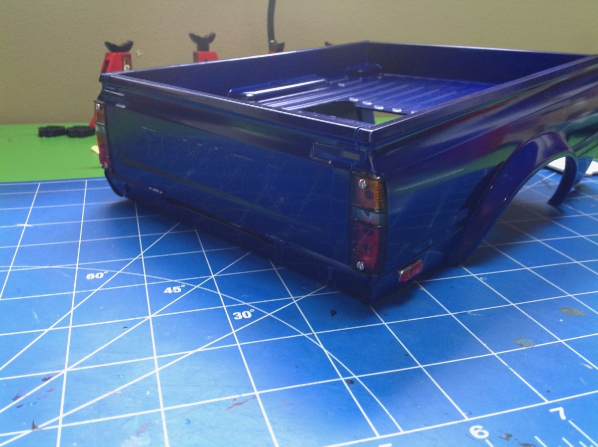
Step 43 installs a bunch of detailed lighting bits on the body including the front and rear side markers and the tail light lenses. The tail lights are screwed on from the outside, and the markers are screwed from the inside. I was glad to have mechanical connections and not to have to use much glue here which can screw up the paint.
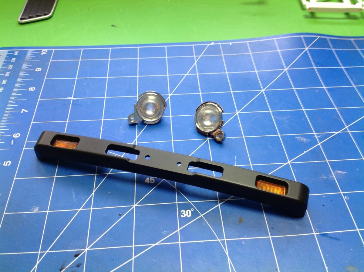
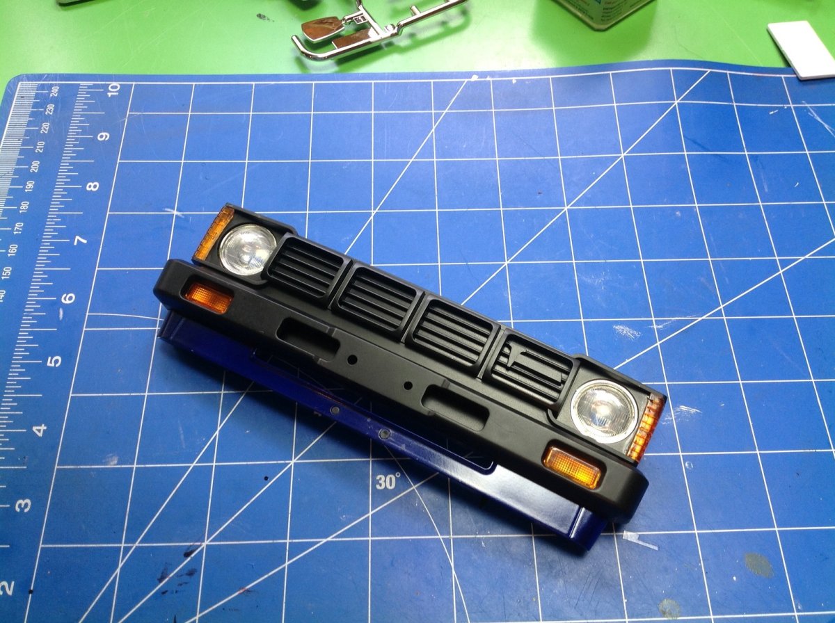
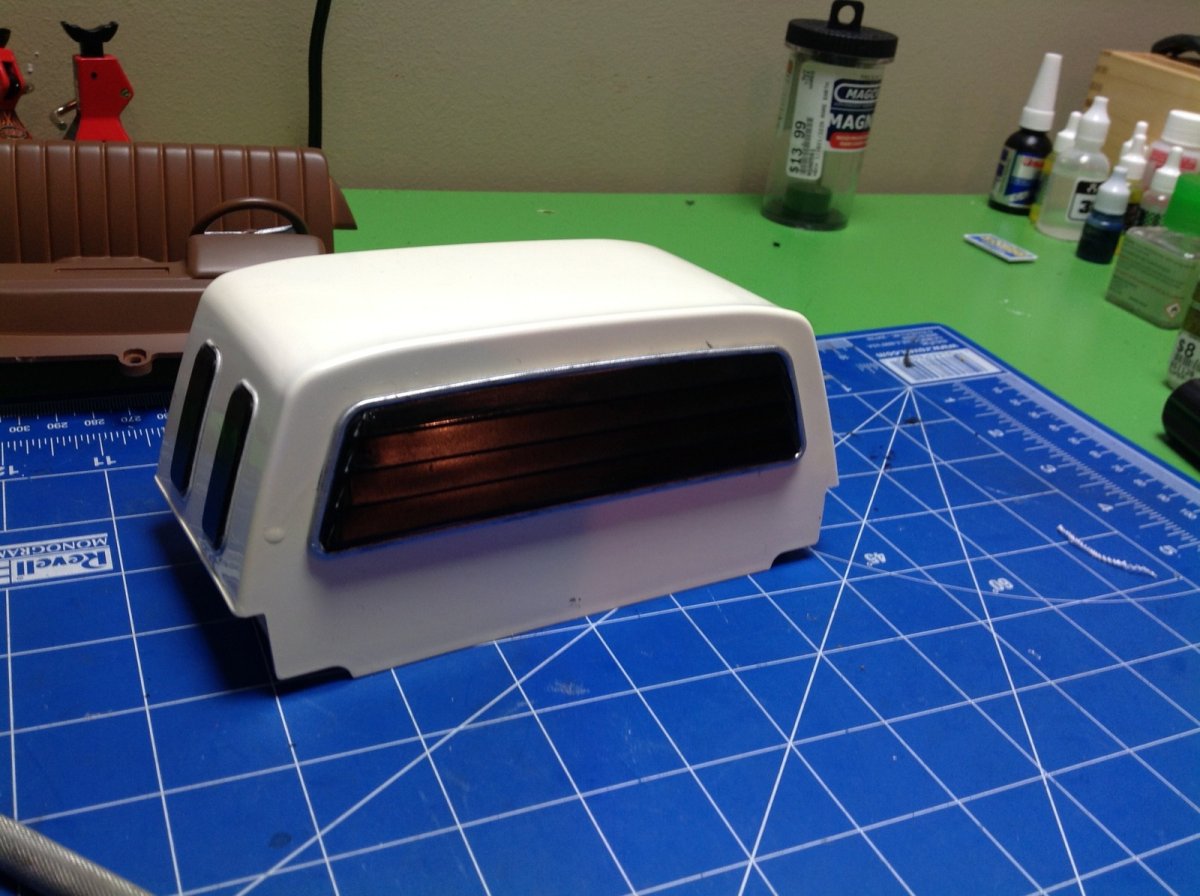
Steps 44 and 45 build the headlight buckets, the grille, and the front bumper. I painted the turn signal lenses orange before I realized they were actually supposed to be clear, but I actually like the way it looks.
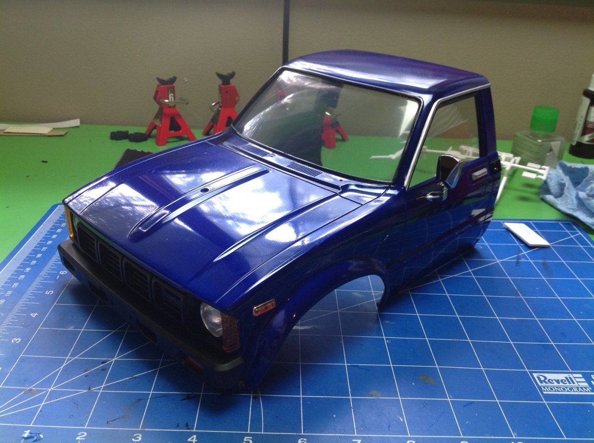
Now the front grille can be installed on the cab and this is really starting to look like a truck. The side mirror is also installed. The kits comes with a passenger side mirror as well, but the instructions say not to install it for some reason.
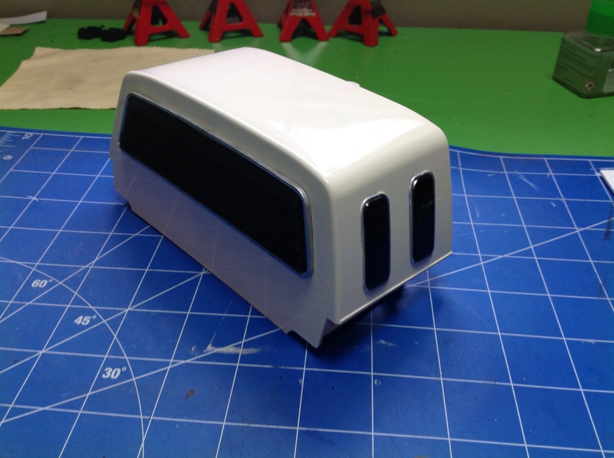
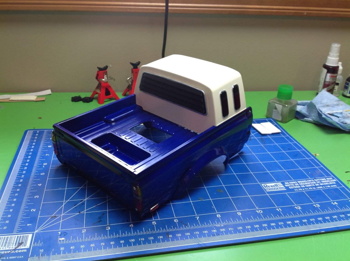
The sleeper is just two parts, the main body and the rear louvers. This part is supposed to be glued on but it doesn't stick very well to the paint. Once the sleeper is screwed to the bed, the back of the body is complete. The opening you see is for the power switch, and the tub area in the rear is for the body pins.
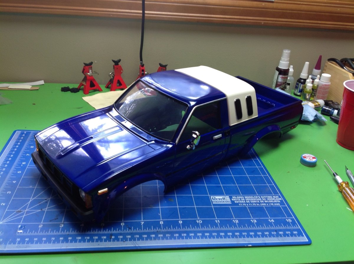
Step 48 attaches the front and rear body halves together with only two screws. They will be further reinforced when the interior is installed.
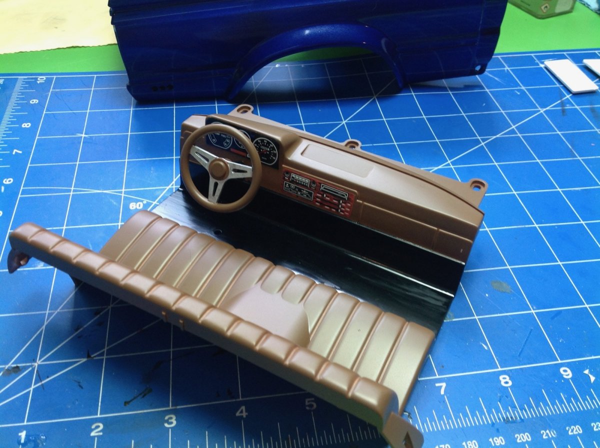
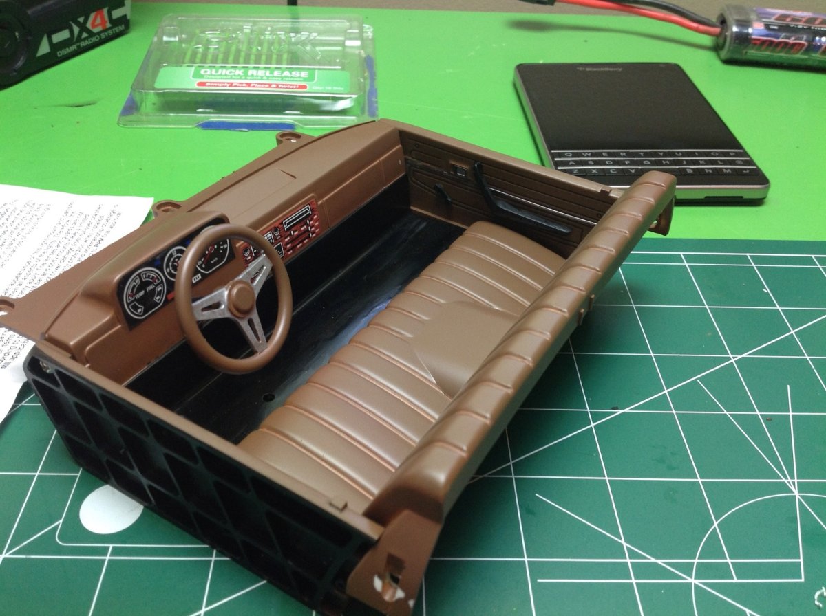
The interior is only a couple of parts, but still looks really good. Most of the detail comes from stickers on the dash for the instrument panel and controls. The seats are nicely detailed and the steering wheel looks great. Installation of the interior does much to add rigidity to the body as well.
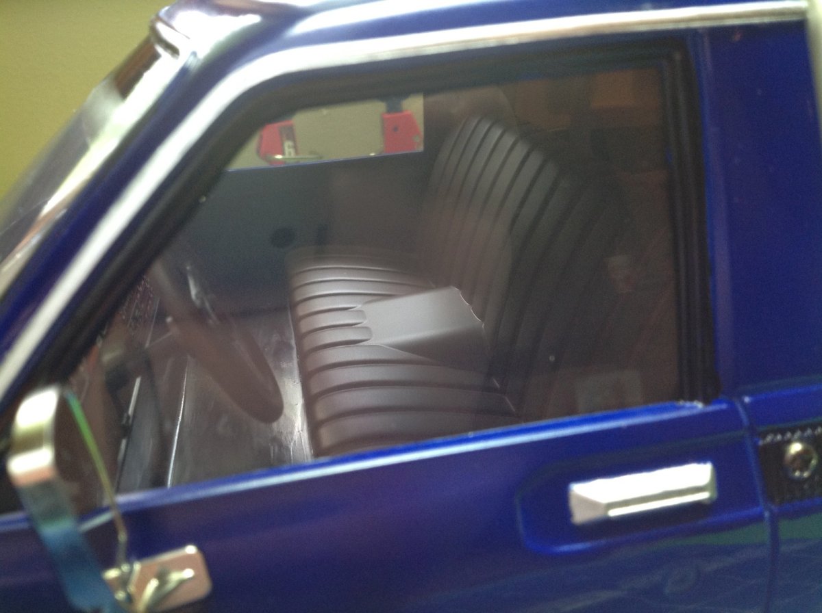
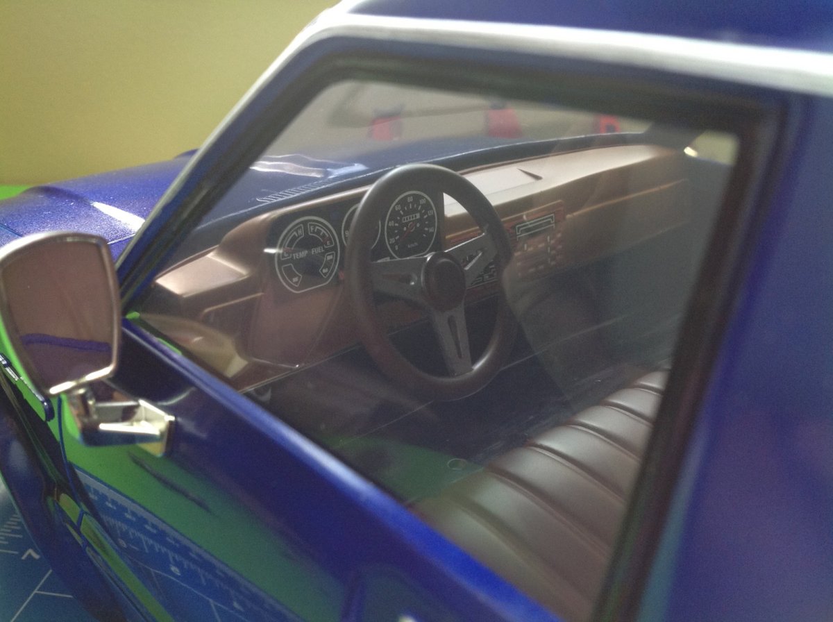
The interior is clearly visible through the large, clear windows. Sadly, the doors do not open.


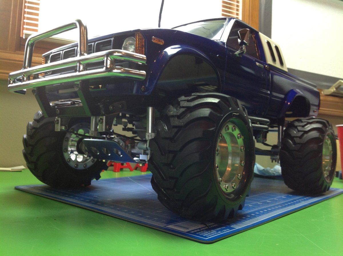
The left hand image shows the completed truck before the stickers were installed. This model comes with a lot of stickers and many of them have that classic '80's Tamiya charm. I wanted this to really look like a scale truck though, so I chose to only install the striping and not all the other graphics. The large stickers are quite a challenge to install because they have to wrap around details like the marker lights and therefore need to be aligned perfectly. There are also some really nice, intricate metal transfer decals for the logo. After the stickers were on I wanted a nice glossy clear coat. I wasn't happy with the level of gloss in Tamiya clear, so I bought a Model Master oil based lacquer. This produced a beautiful deep clear, but is also reacted chemically with the paint and caused some runs on the wheel arches and on the windows of the sleeper. I have decided they are artistic character patches. Both of these images also show many of the upgrades which I'll be discussing in the next chapter.
Upgrades!
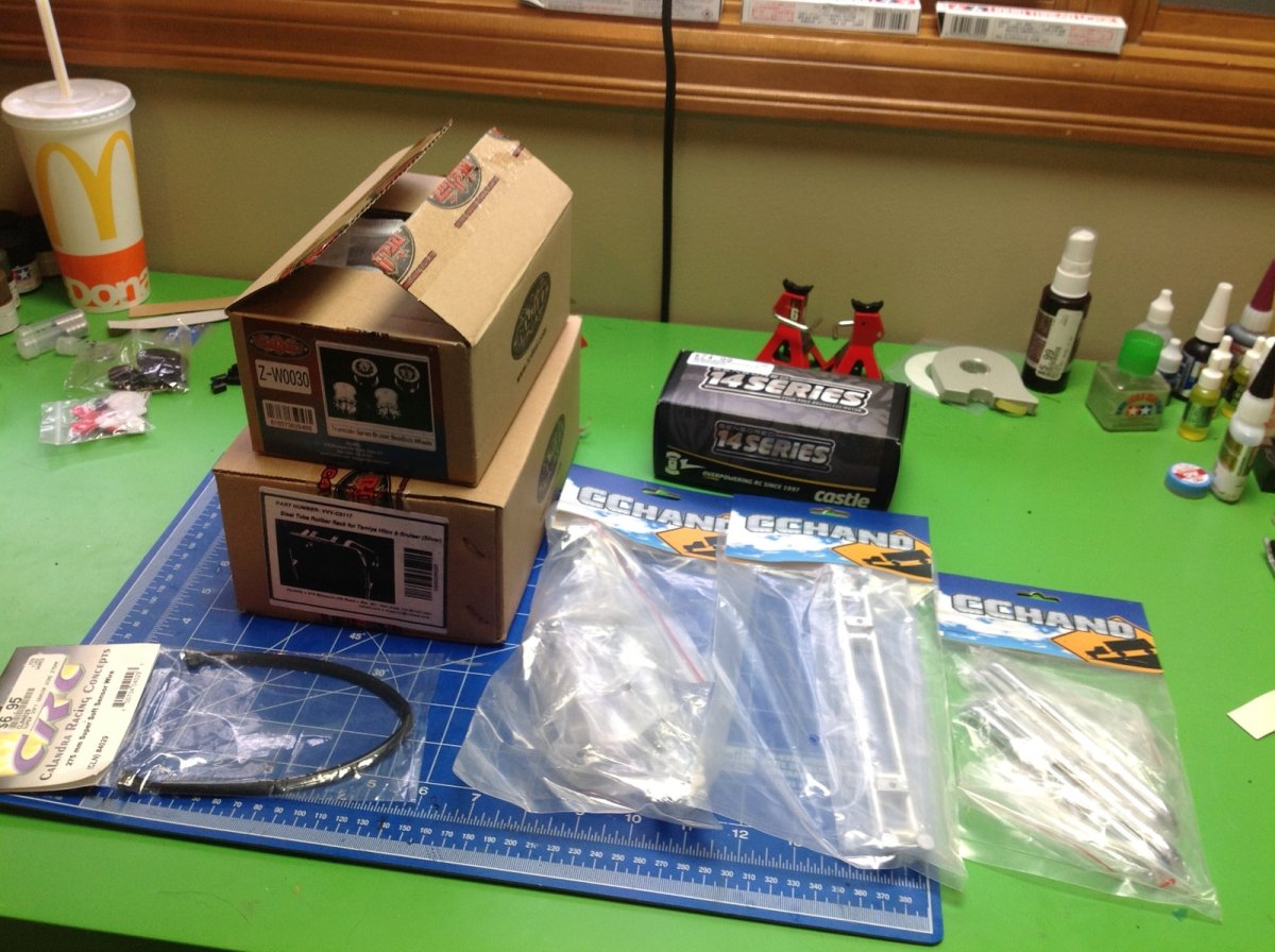
Here sits a pile of upgrades that I planned before I had even started to build the model. They include a bunch of steel bumper parts from RC4WD, aluminum beadlock wheels, and a brushless system from Castle. Buying upgrades before ever even trying the stock model is not a great idea because you might not buy the right things or you might get things that won't work. I ran into a series of problems with this strategy.
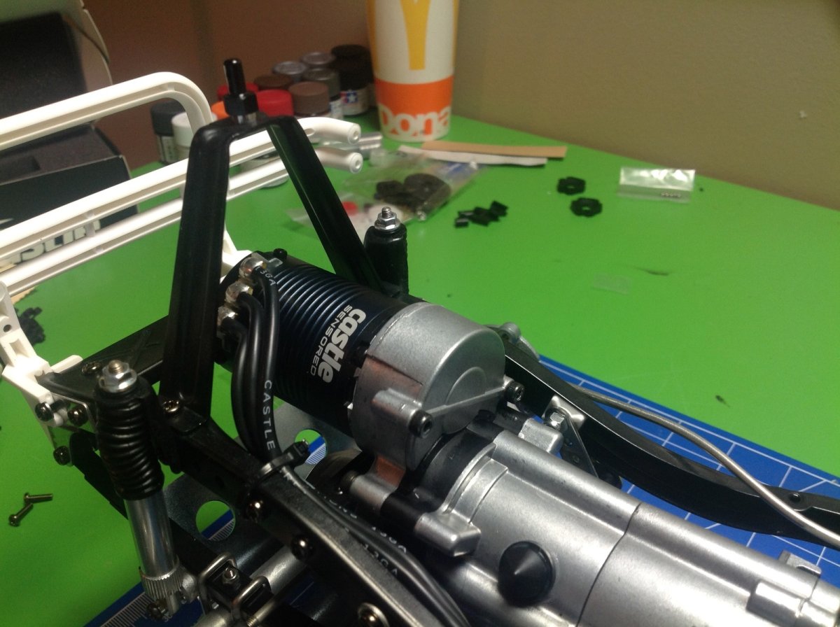
Let me start by saying that a brushless system on this truck is completely unnecessary. It was still fun though. The truck is pretty slow stock, even in high gear. That's actually a good thing though, because the suspension can't handle high speed. Since many of the modern Tamiya kits come with TBLE-02s speed controllers which work with sensored brushless motors and since I had never used a sensored motor before, I decided to give it a shot. I used a Castle 2280kV motor. The first problem I ran into is that the motor is in the very front and the controller is in the very back. The longest sensor wire you can buy is 270mm and that wasn't long enough. That means I had to buy 2, cut them in half, and carefully splice the wires together. I didn't even have any heat shrink tubing so the resulting wire is a kluge but it works and I will never touch it again.
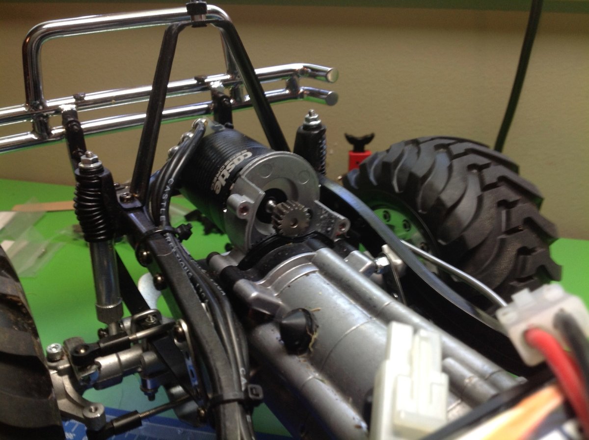
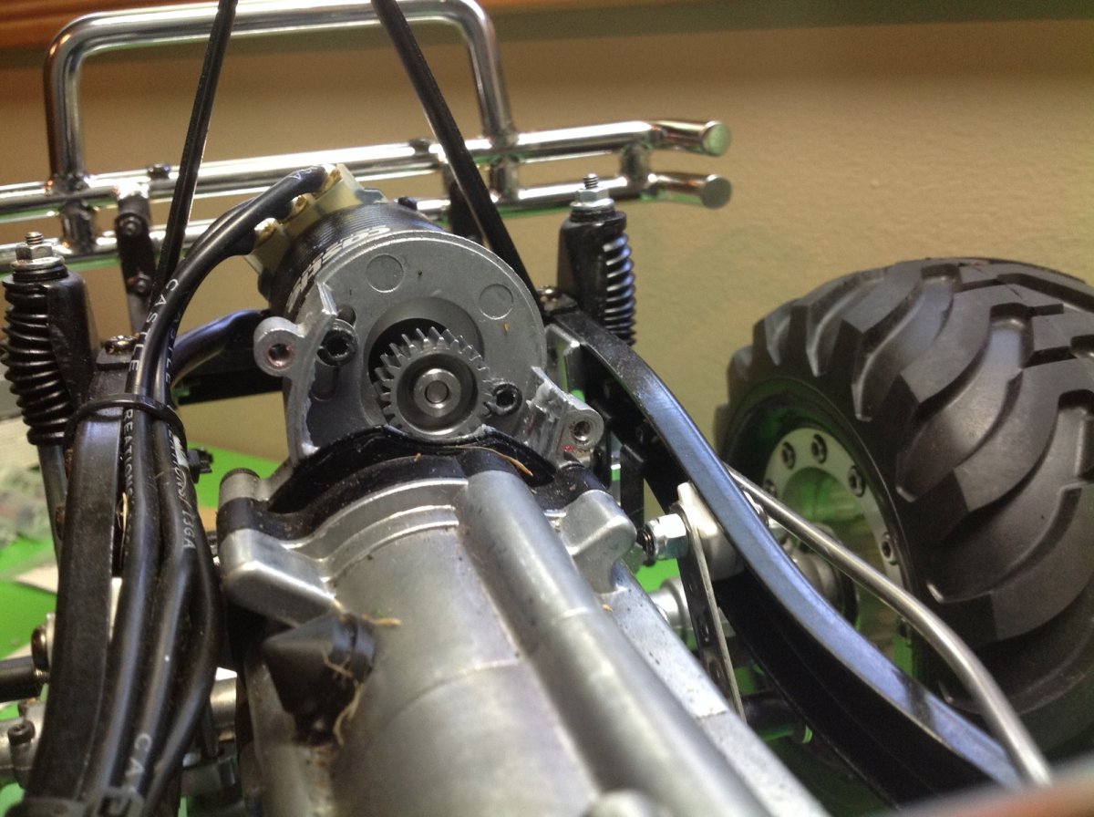
With a 2280kV motor on 7.2 volts, the truck wasn't really any faster than stock. On the plus side, it operates almost totally silently. There is no gear or motor noise. Still, I figured I could put a larger pinion in there without hurting anything. I went from the stock 19 tooth up to a 23 tooth steel pinion. I think this combination is perfect for this model. I love the speed and torque. There is adjustment space for an even bigger pinion, but Robinson doesn't make anything with more than 24 tooth in 0.6 mod pitch.
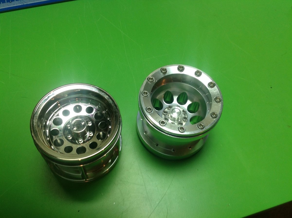
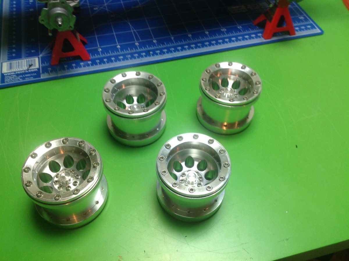
RC4WD offers a beautiful set of aluminum beadlock wheels specifically for the Bruiser and I had to have them. You can see the original plastic (and very nice) wheel on the left and the aluminum on the right. This was another totally unnecessary upgrade, but I really like the solid feel of the aluminum and, in case I needed to justify myself, they help lower the CG and prevent rollovers.
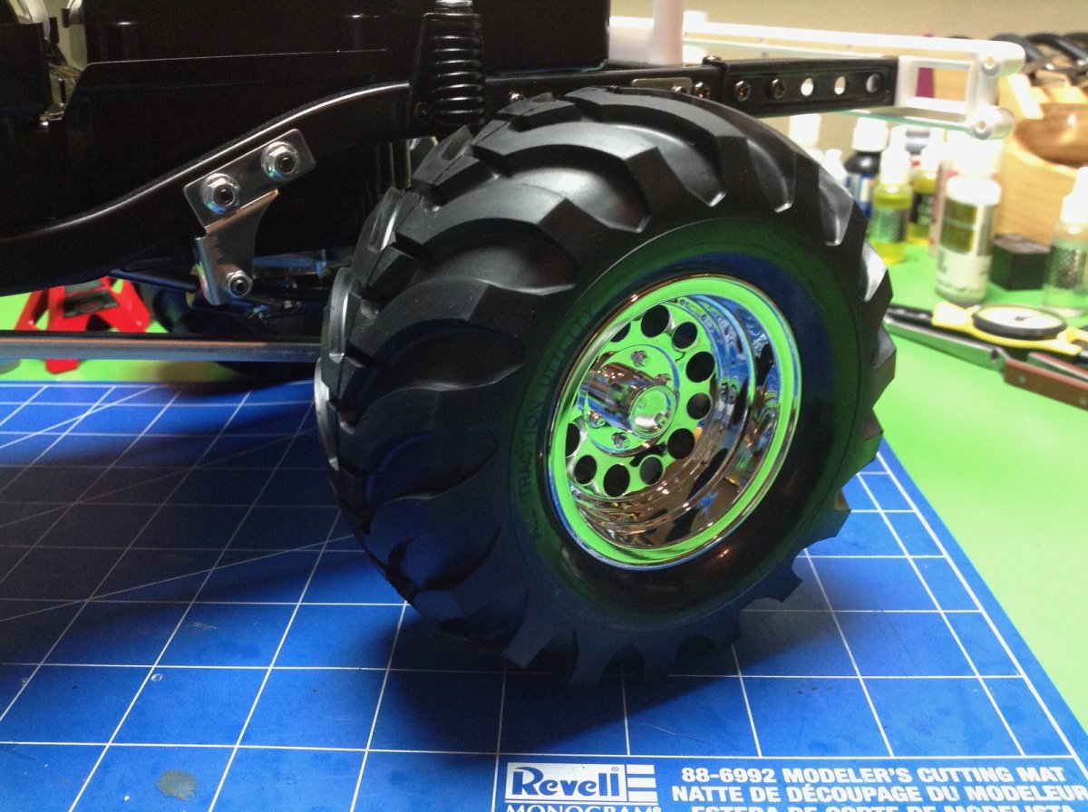
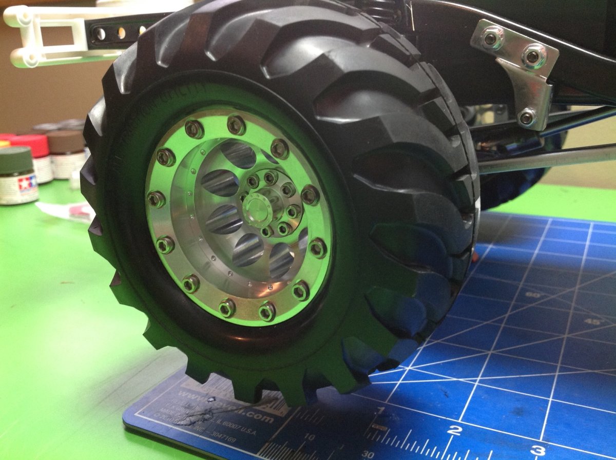
Here is the before and after wheel with tires mounted. You can see that the stock wheel actually looks really good and you can't even tell it is plastic. The aluminum wheel hides the mounting nut behind a center hub which looks good but makes them difficult to remove.
Now all four are installed and I was able to go drive the truck around the yard. It is really a good machine with easy characteristics, but it is neither a speed demon nor a hard core crawler.
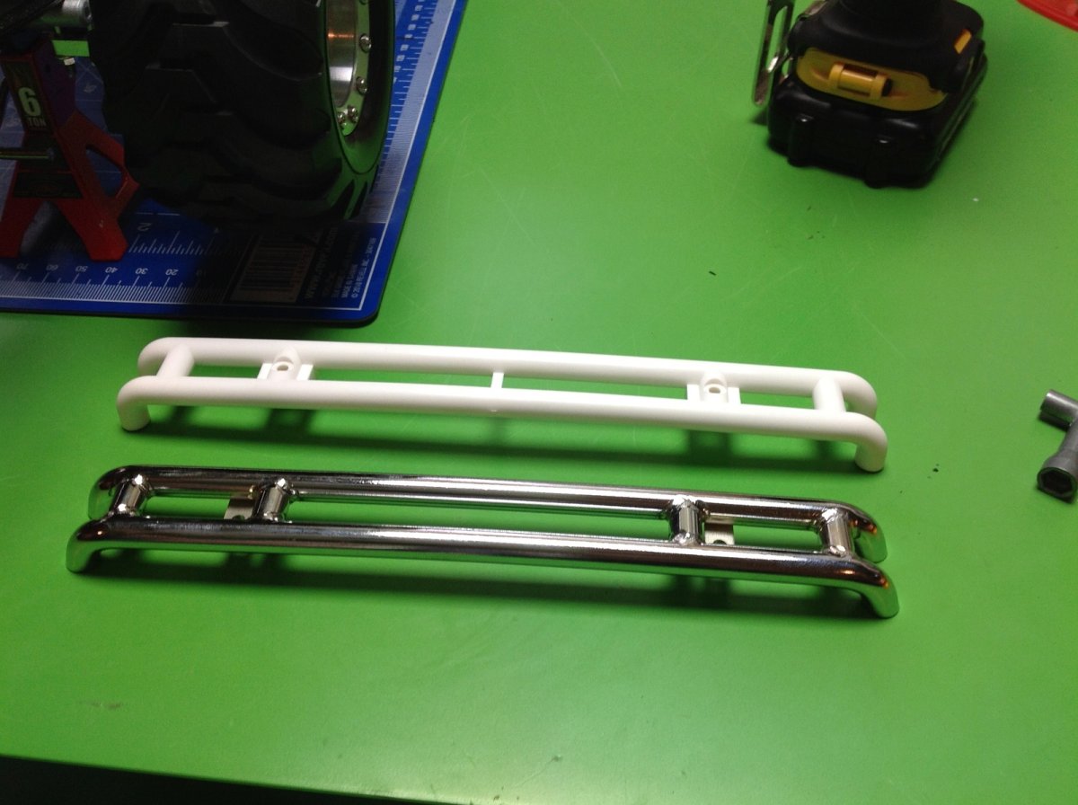
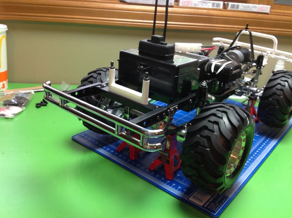
All of the bumpers on the model are white, very flexible plastic. This is probably a good thing for bumpers, but since RC4WD offered tube steel versions, I had to have them. This shows the stock rear and upgraded bumpers.
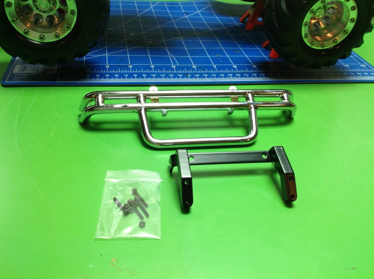
Here is the steel front bumper. I am sorry to say that the quality isn't great. The holes are not drilled quite evenly and the result is that the bumper sits a little crooked on the chassis. It is not very noticeable in the picture, but once you put the body on you can see that they are not aligned.
Now the front and rear bumpers have been installed, and so have a pair of steel skid plates below the doors. There's a lot of metal on display here. The skid plates are actually attached to the body and come off with it.
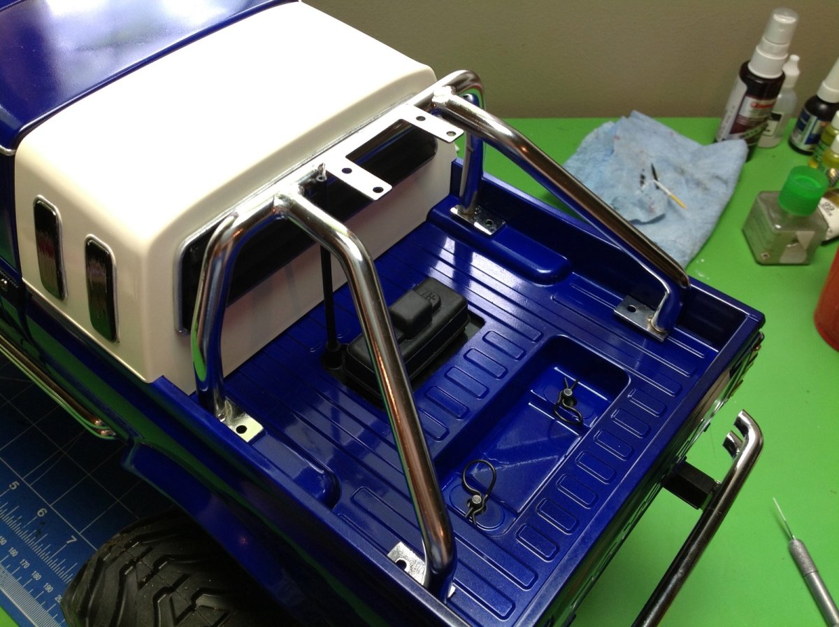
The stock Bruiser never came with a roll cage, but the Mountaineer which came out later and used the same body did. That means this aftermarket steel roll cage should fit, right? Not quite. The sleeper means it needs to sit farther back. You can see that the front mounting feet are up on a little pad, but there are no pads in back. This makes the whole cage tilt backward.
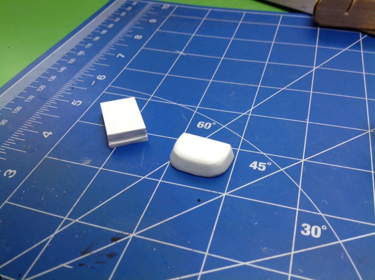
I used some sheet styrene to fabricate some rear pads to look mostly like the front pads. I just glued 4 layers together and then sanded them. The left image shows before and after sanding. The right image shows the installed roll cage, now sitting straight. It also attaches to the body like the sliders, so that makes the whole body very heavy.
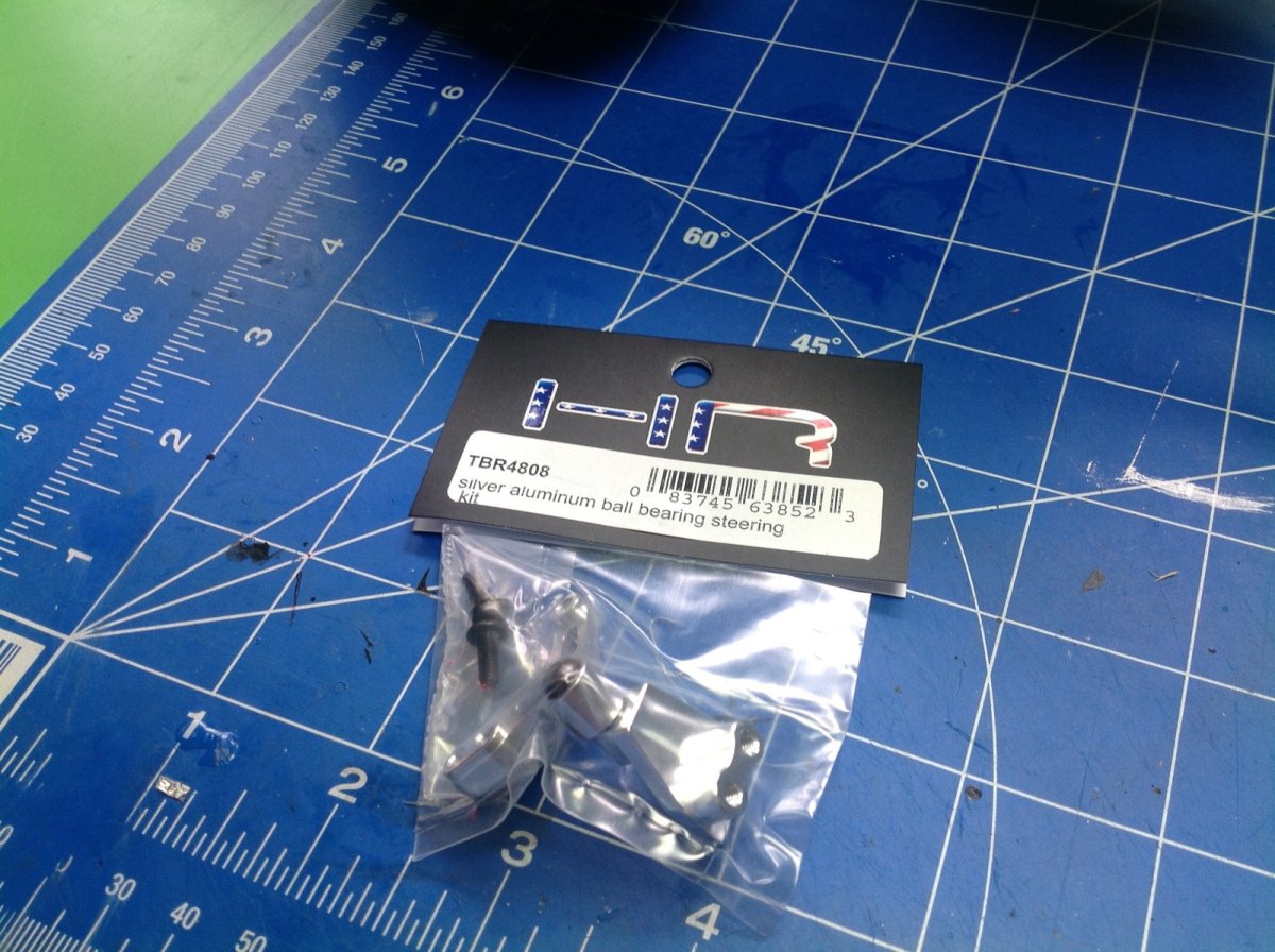
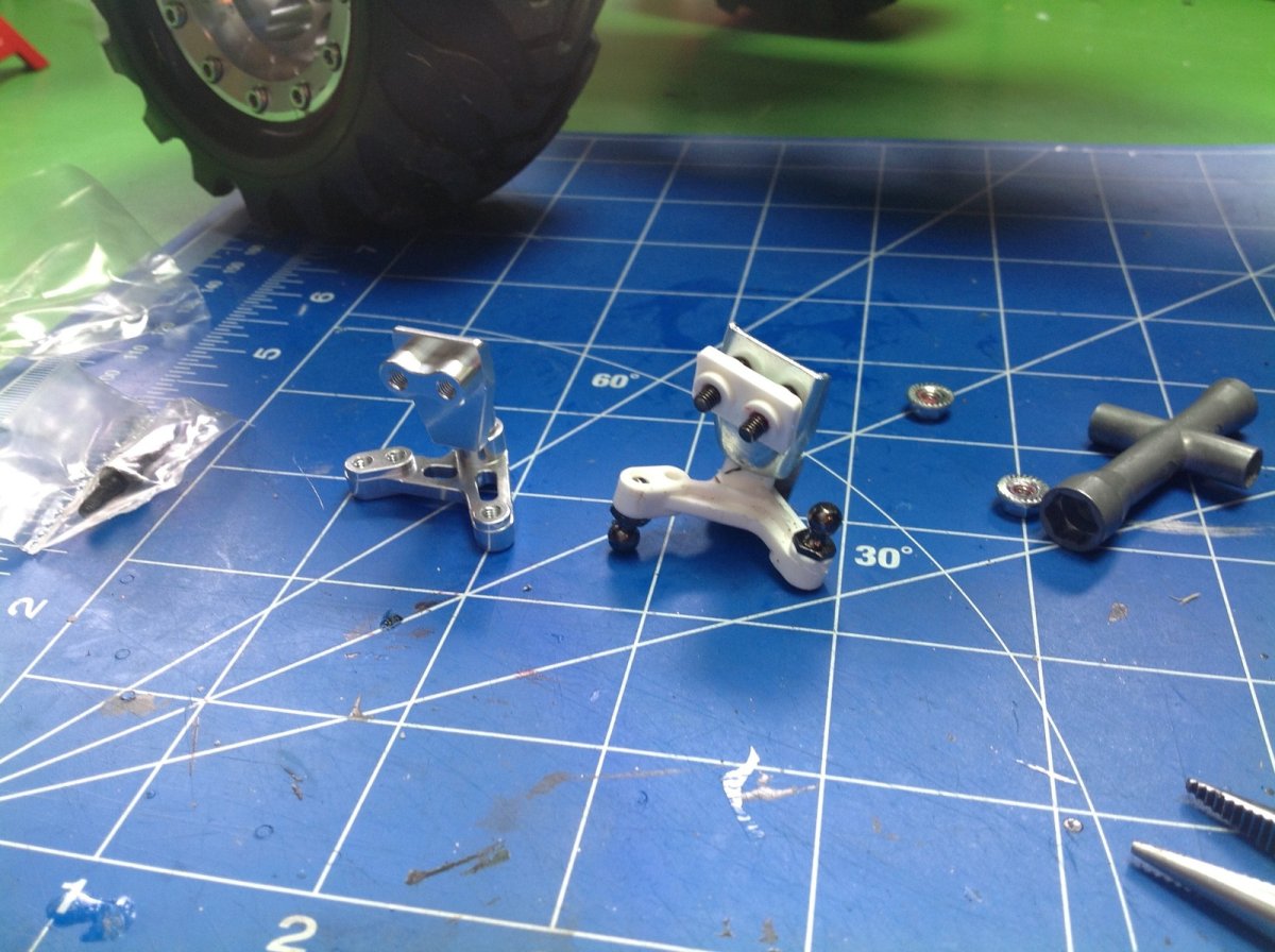
Most of the upgrades so far have been for fun, but the steering crank is something that really needs to be changed. I don't know why they used a soft plastic crank, but it is completely inadequate for turning the wheels. There is so much flex in the crank that the steering wobbles all over. Luckily, Hot Racing offers an aluminum crank. You can see the old and new parts in the right hand image.
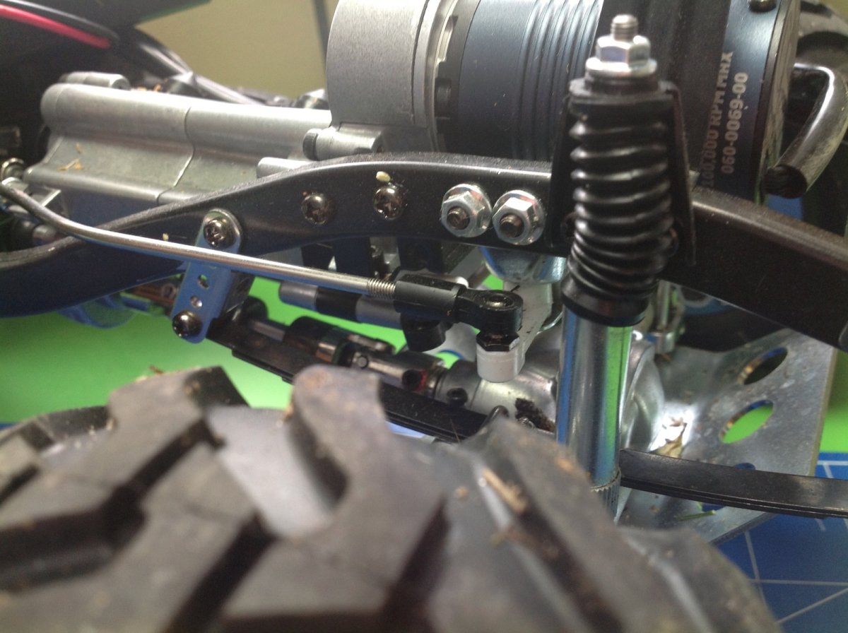
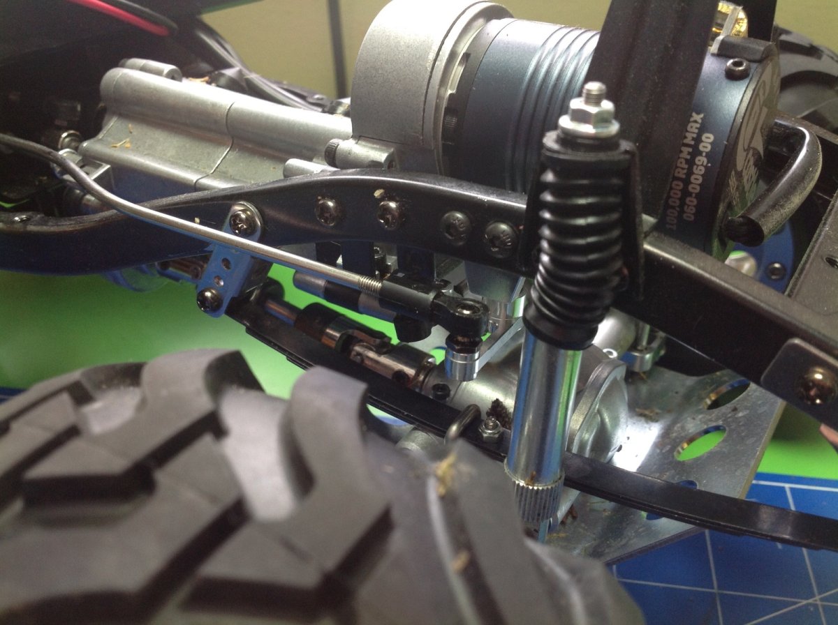
You have to look closely to see that the crank has been changed, but it made all the difference in the world. The truck now turns on a dime with the new steering crank. Best upgrade I've made.
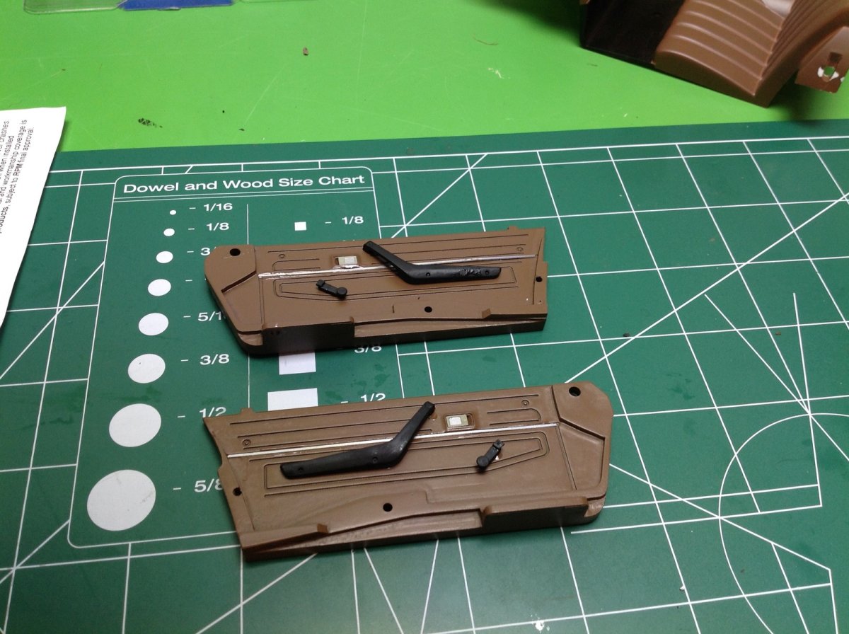
When I first bought the truck this next upgrade didn't even exist, but the detailed interior door panels from RC4WD that came out and are very nice. You can see how much they improve the realism of the interior. At least as importantly, they ended up hiding all of the wires that I had to attach to the side walls for lighting. I still need a scale driver though .....
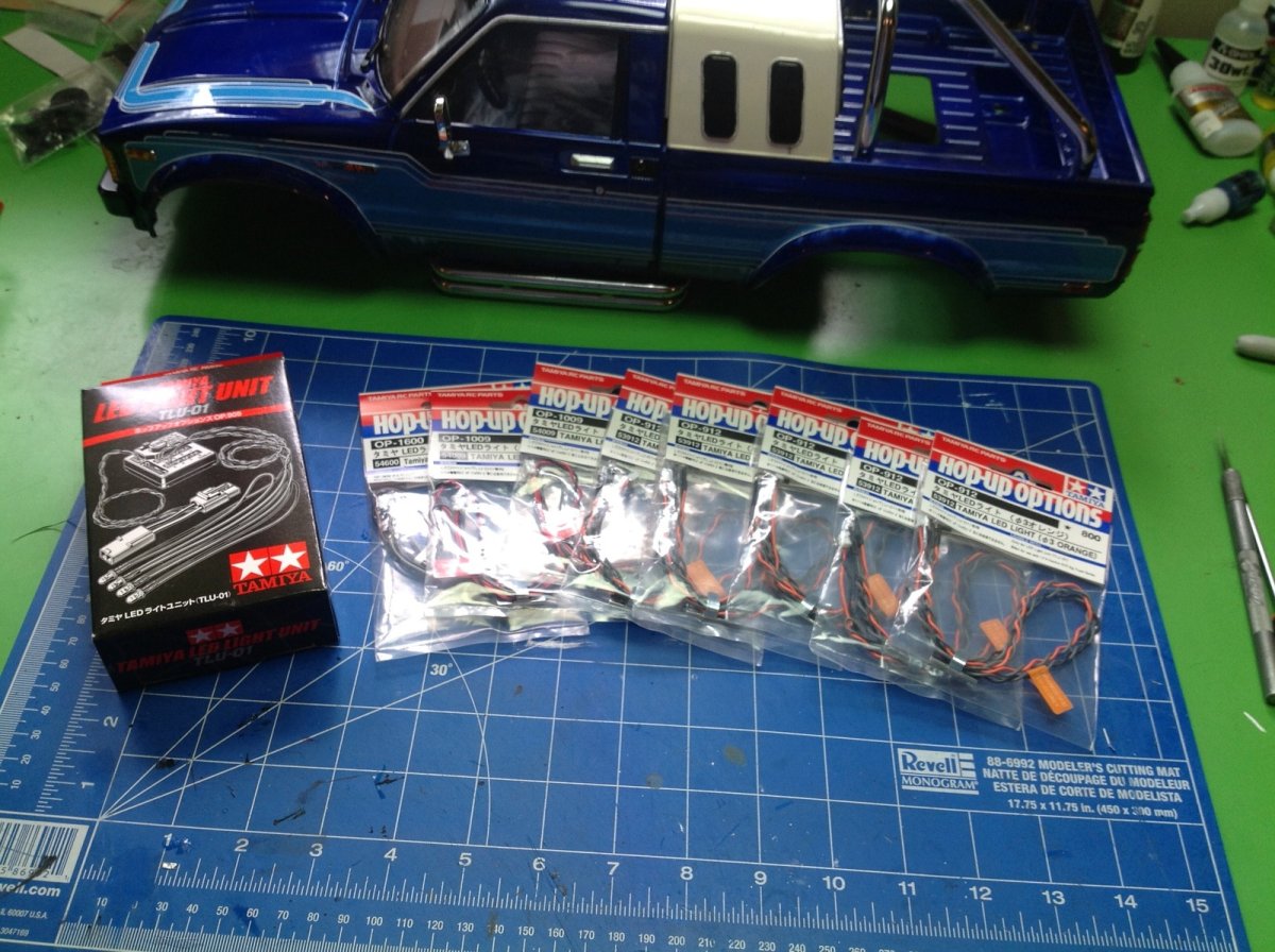
From the beginning I knew I wanted to add lighting to this model. All of the light buckets are already part of the body, so it is just screaming for an upgrade. But how far to go? The stock body has these light buckets:
- 2 headlights
- 4 tail lights
- 4 side marker lights
- 2 front marker lights
- 4 turn signals
- 2 reverse lights
If you are counting that makes 18. The Tamiya TLU-01 light unit supports 16. So which should I leave out? My original choice was to leave out the reverse lights since I didn't want them on all the time anyway, but I later came up with a better solution.
Here's my first attempt at a lighting installation. I was not at all happy with the stretch in the wires and I knew they would up getting snagged on something. Still, it was good enough to try it all out.
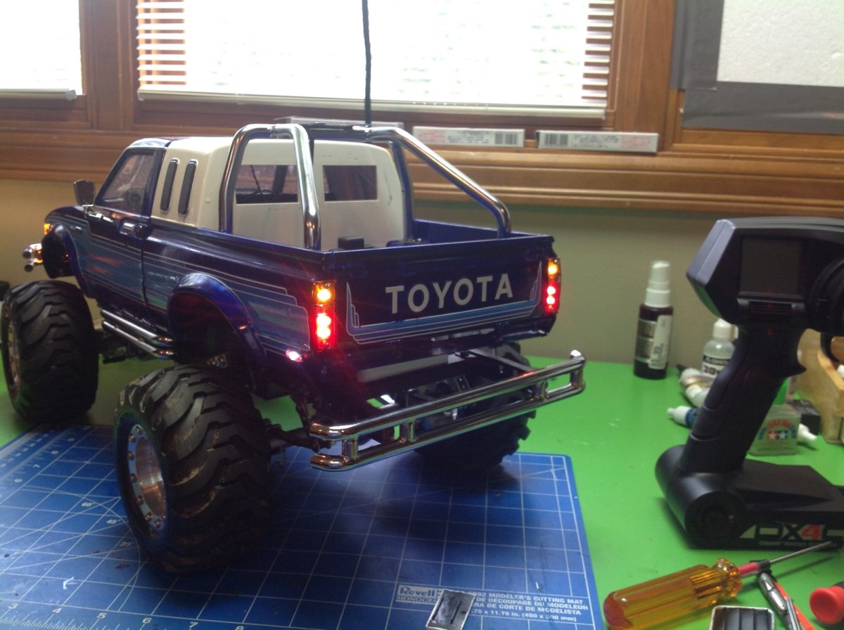
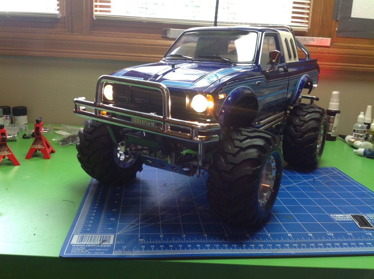
Here's my first edition light system on the truck. Note that I used halogen colored headlights instead of white which I think looks much better. Tamiya had just released these so I was one of the first to try them. I think they look perfect for a scale appearance.
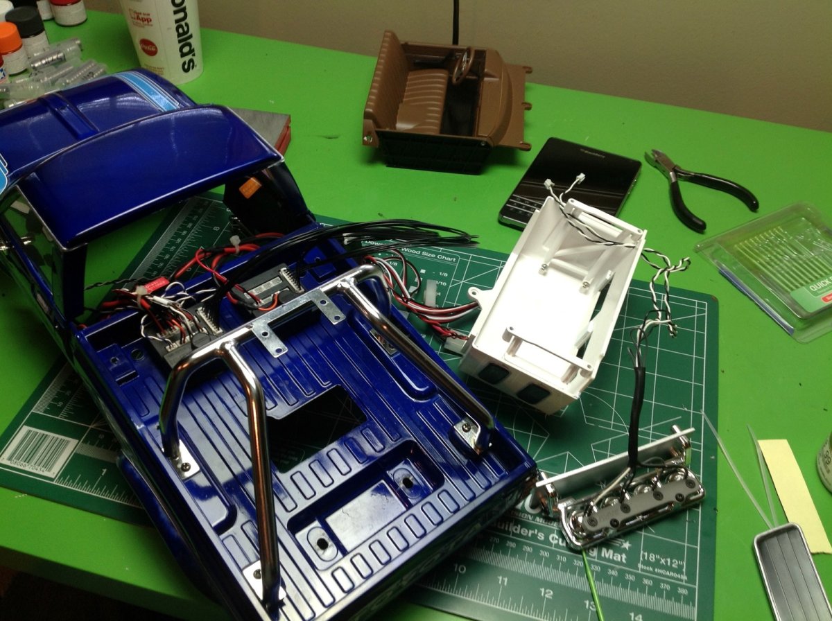
My lack of using two of the light buckets was bothering me, so I came up with a crazy solution. You can use two TLU-01 light units and control them with a TLU-02. This costs a fortune, but it means that I would now have 14 extra light channels instead of being two short! I couldn't think of a use for all of them, but I did decide to install some fog lights on the front bumper and on the roll bar. This picture shows some of the wiring before the TLU-02 arrived. You can see the light bar lying on the right.
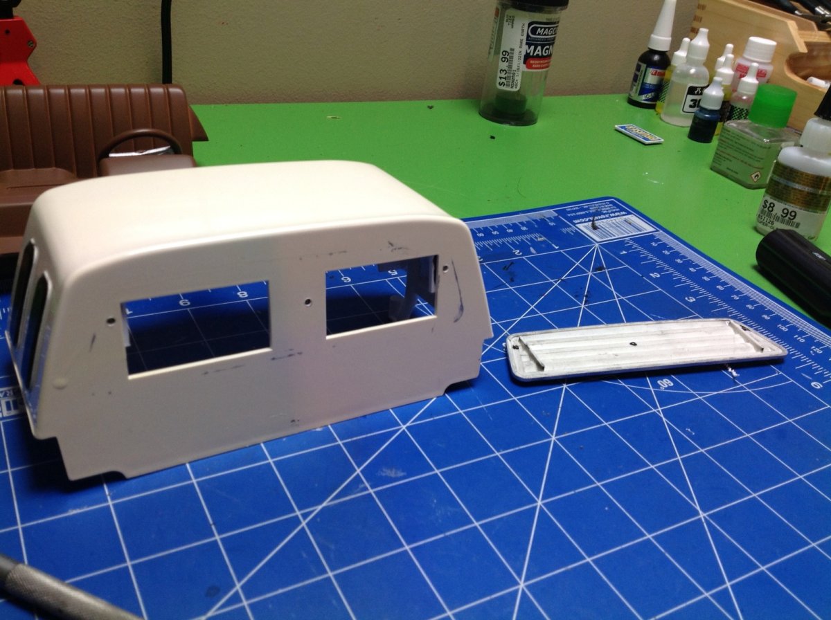
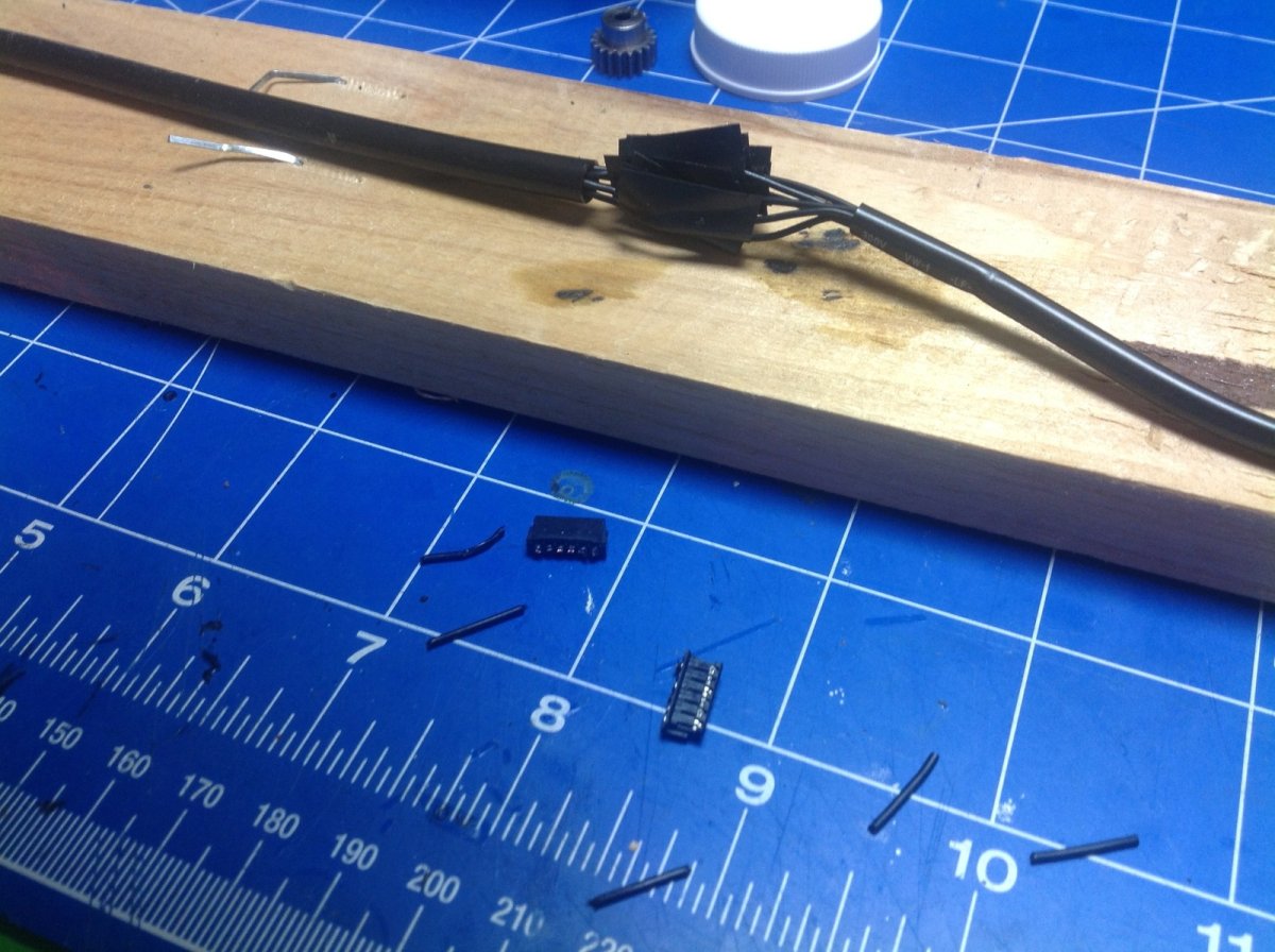
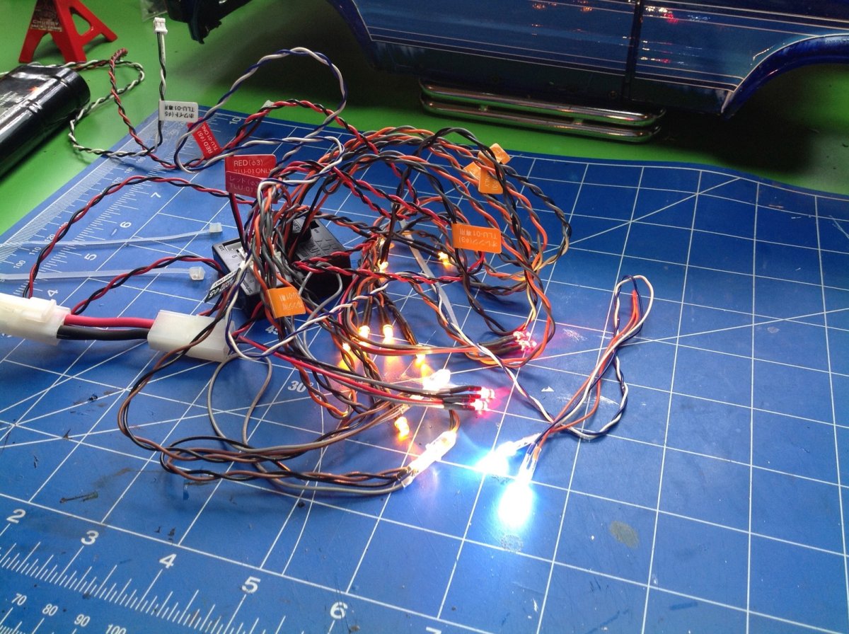
Figuring out where to hide all these electronics was a problem, so I decided to use the sleeper. It has plenty of room for all three light controllers, but it introduces two new problems. First problem is that the TLU-02 needs to be connected to the servo wires to control the lights. To solve this I needed to use a bunch of extensions to go from the servo and ESC to the controller, then back out to the receiver. They all needed to have connectors so I could still remove the body. The other problem is that you need to access the TLU-02 to turn it on and change modes. I solved this by removing the louver on the back of the sleeper and then converting it to install with magnets. This way I can easily remove it and reach my finger inside to switch on the lights!
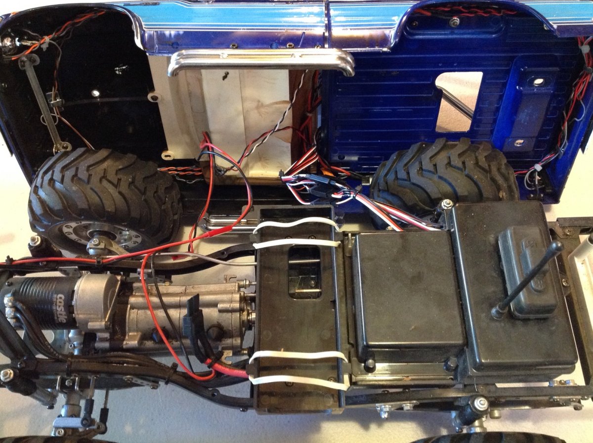
The TLU-02 needs to be connect directly to the battery, so I also needed some detachable wiring for that, and yet another connector for the front fog lights which are connected to the chassis and not the body. Finally, I had to solder extensions onto many of the LED wires because they were not long enough. It was probably a good two weeks of soldering before I got everything done and looking nice. The image on the left shows the final wiring. You can see the leads going from the battery and from the front fog lights to the body through JST connectors. There is also a bundle of 4 servo extensions. Everything is routed neatly enough and hidden that you hardly know what a mess it was. When everything is hooked up and working, it looks like the picture on the right. The headlights are halogen colored, but the foglights are white. At one point I also had 4 more fog lights on top of the roll cage, but I didn't like the way they looked. They ruined the scale appearance somehow so I took them off and also pulled off the ugly brazed brass light mounting tabs from the roll bar.
There's one little bit of hidden trickery. The TLU-02 supports a total of 4 running lights, but I needed 6. This means I needed to wire the last pair into an AUX channel. Sadly, all the AUX channels flash at full throttle which looked stupid. To solve this, I set my radio to 120% on the throttle channel and then calibrated the TLU-02 using the radio. When I set the radio back to 100%, the TLU never registers full throttle and therefore never flashes! Just what I needed. The turn signals blink when turning, the hazards blink when stopped, the brake lights get brighter when braking, and the reverse lights come on when backing. There are 3 modes so you can have only the marker lights on, add the headlights, and then add the fog lights. I usually run in Mode 2 with the fog lights off unless it is night.
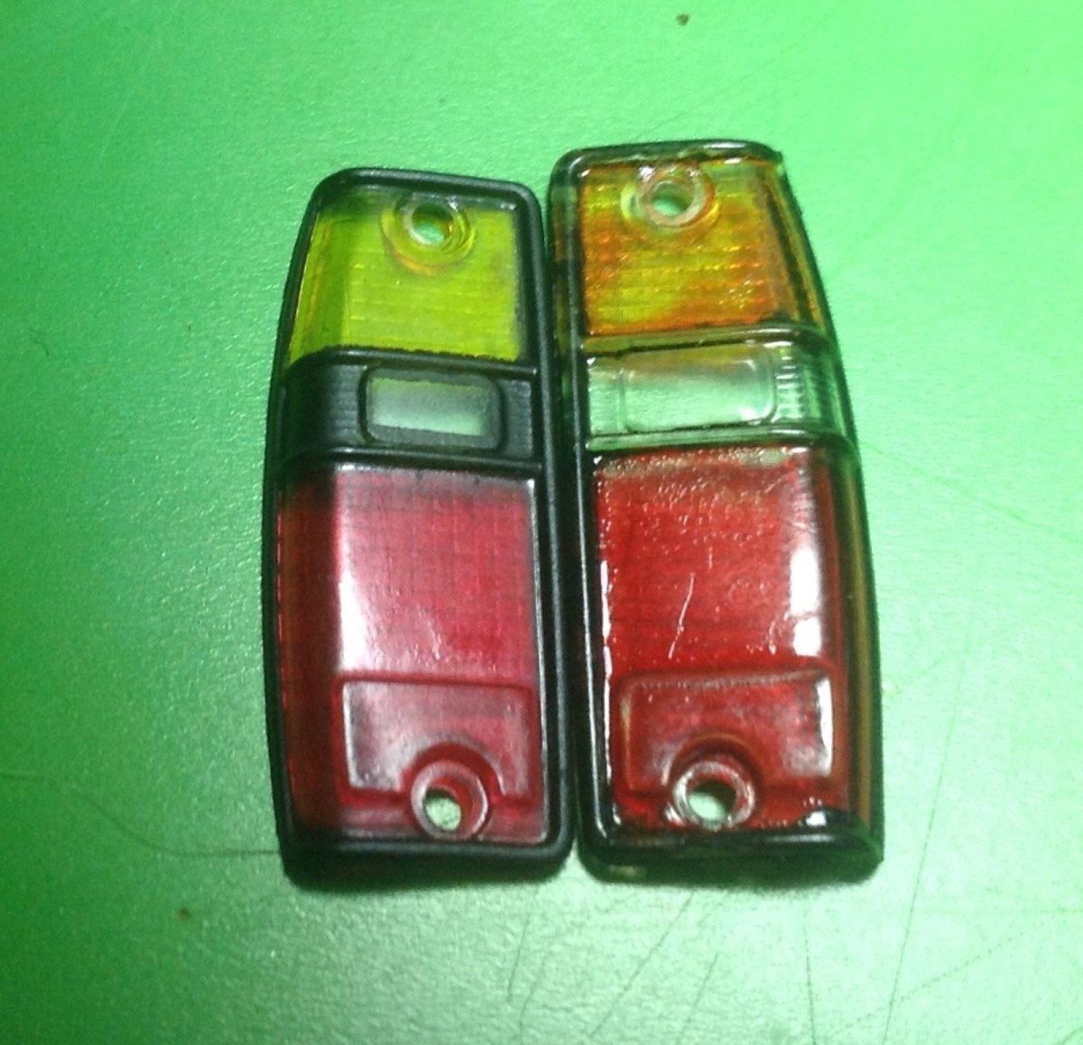
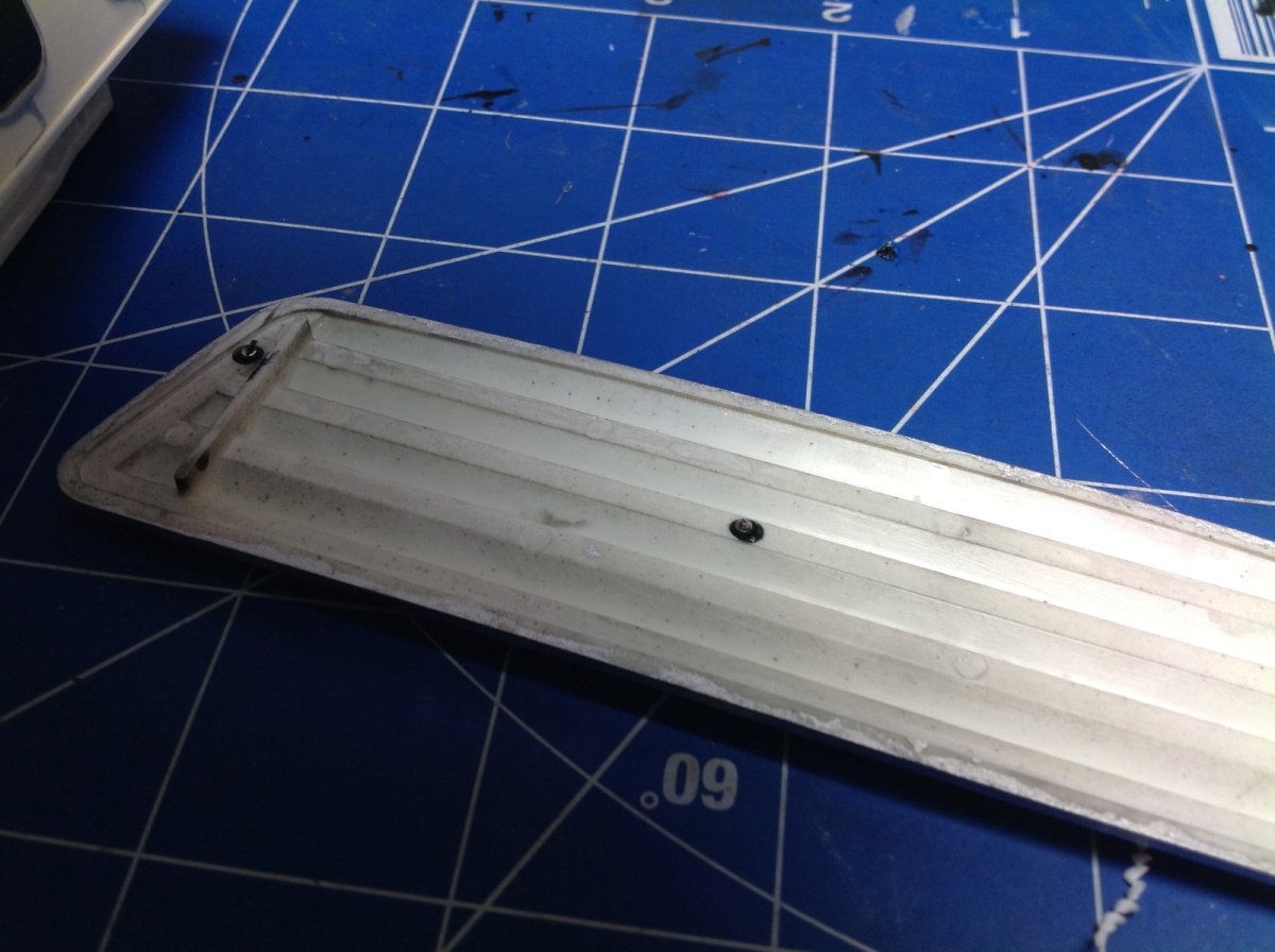
This image shows the very expensive RC4WD detailed tail light lens (left) compared with a stock lens (right). Sadly, as you can see, they are not the right size. They are too small so when you install them they look bad. I had to revert to my stock painted versions. These are really for the RC4WD Mojave body and should not be advertised for the Bruiser or Mountaineer.
Phase 2:
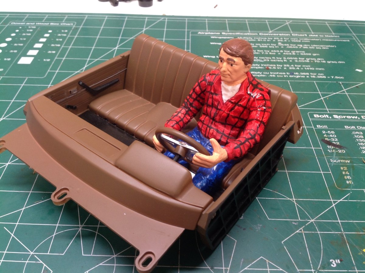
I don't know what took me so long, but I finally got around to putting a driver figure in this truck. This is something that should have been there from the start. My daughter (who has a steadier hand than me) painted the plaid on the flannel shirt. The shiny area on his shoulder is just CA accelerator. It dried flat.
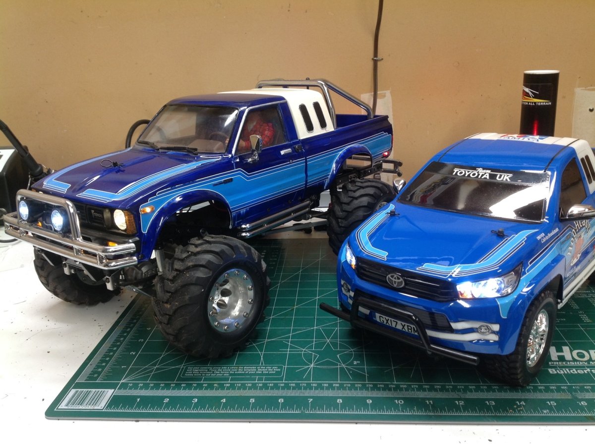
The only final photo I have of the driver installed is this comparison picture with the CC-01 Hilux.
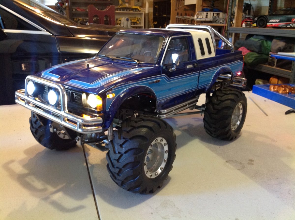
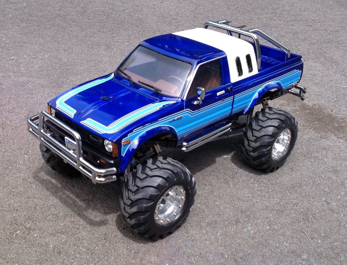
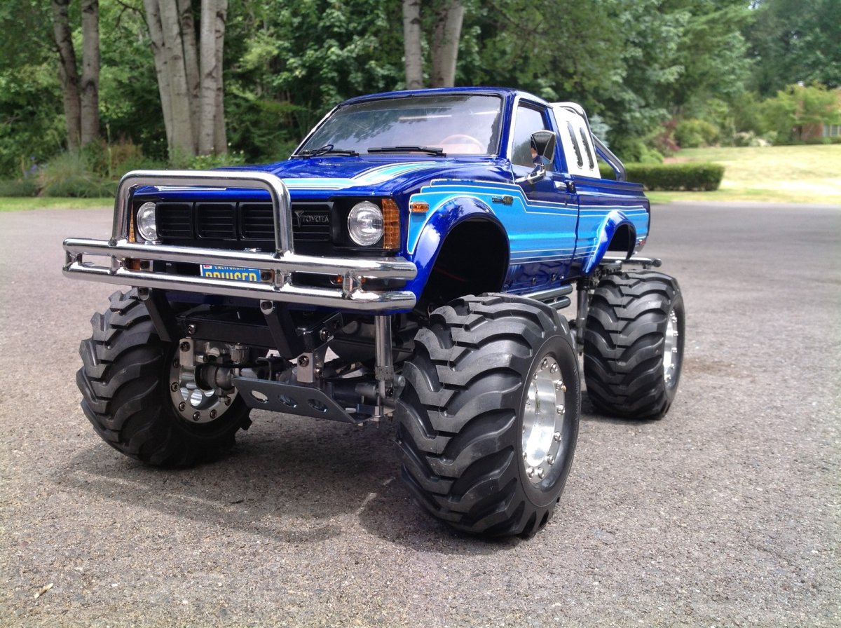
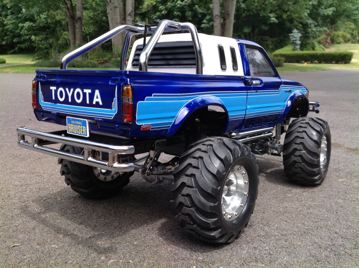
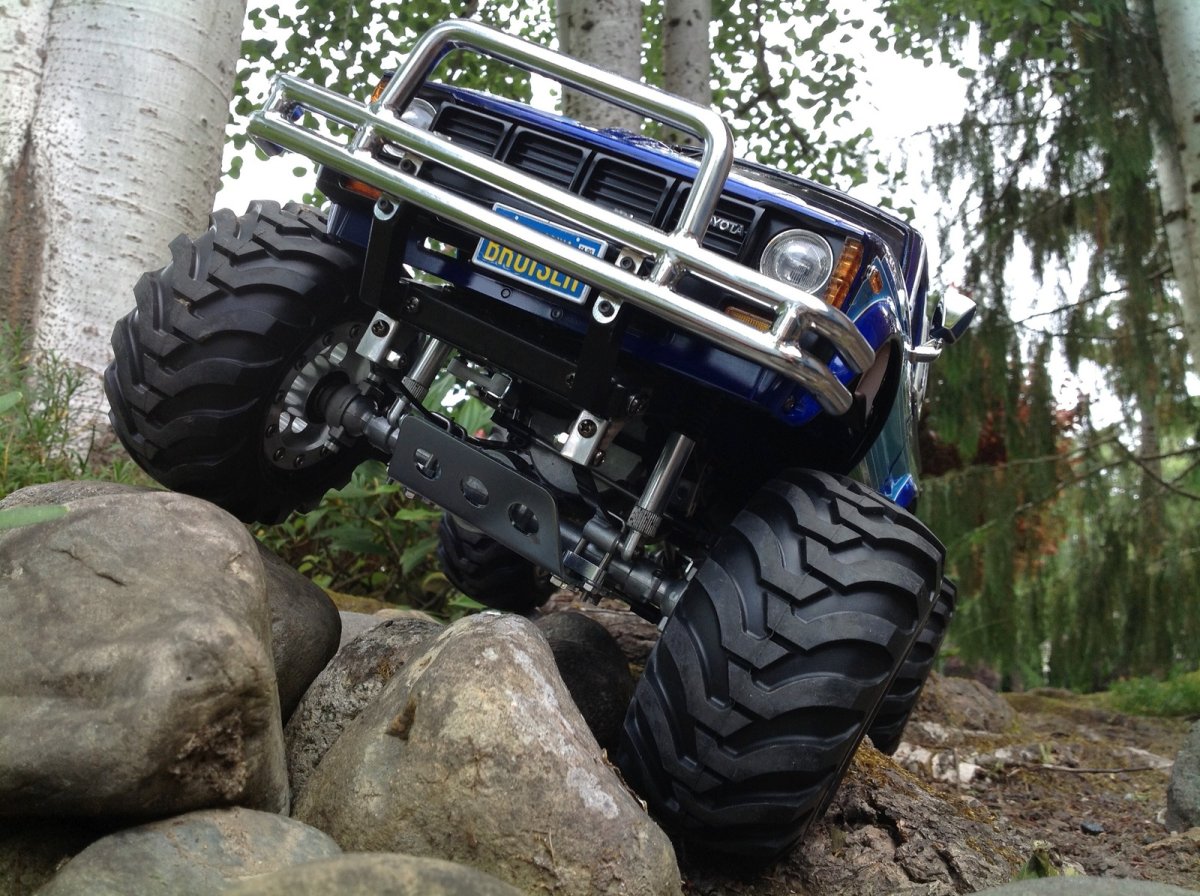
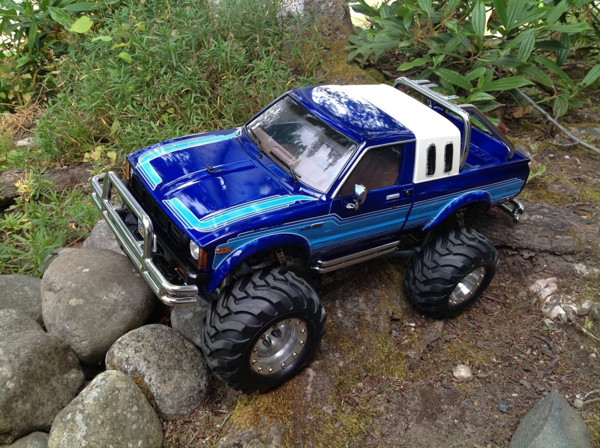
Final Photos
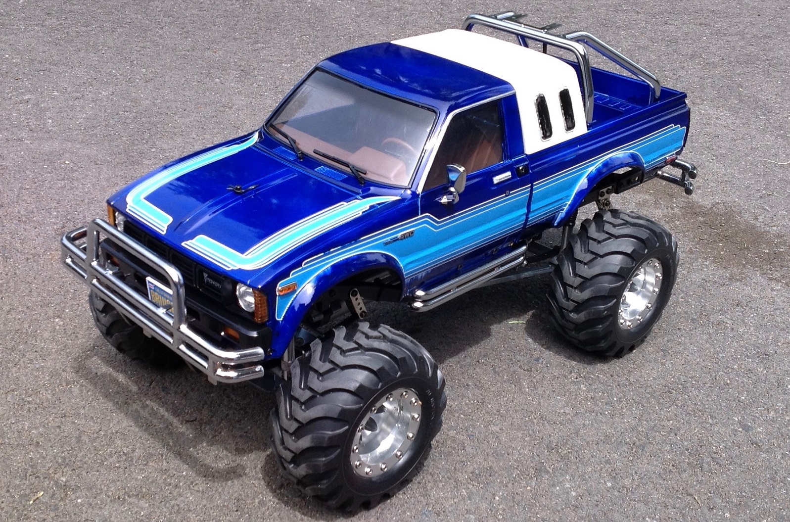
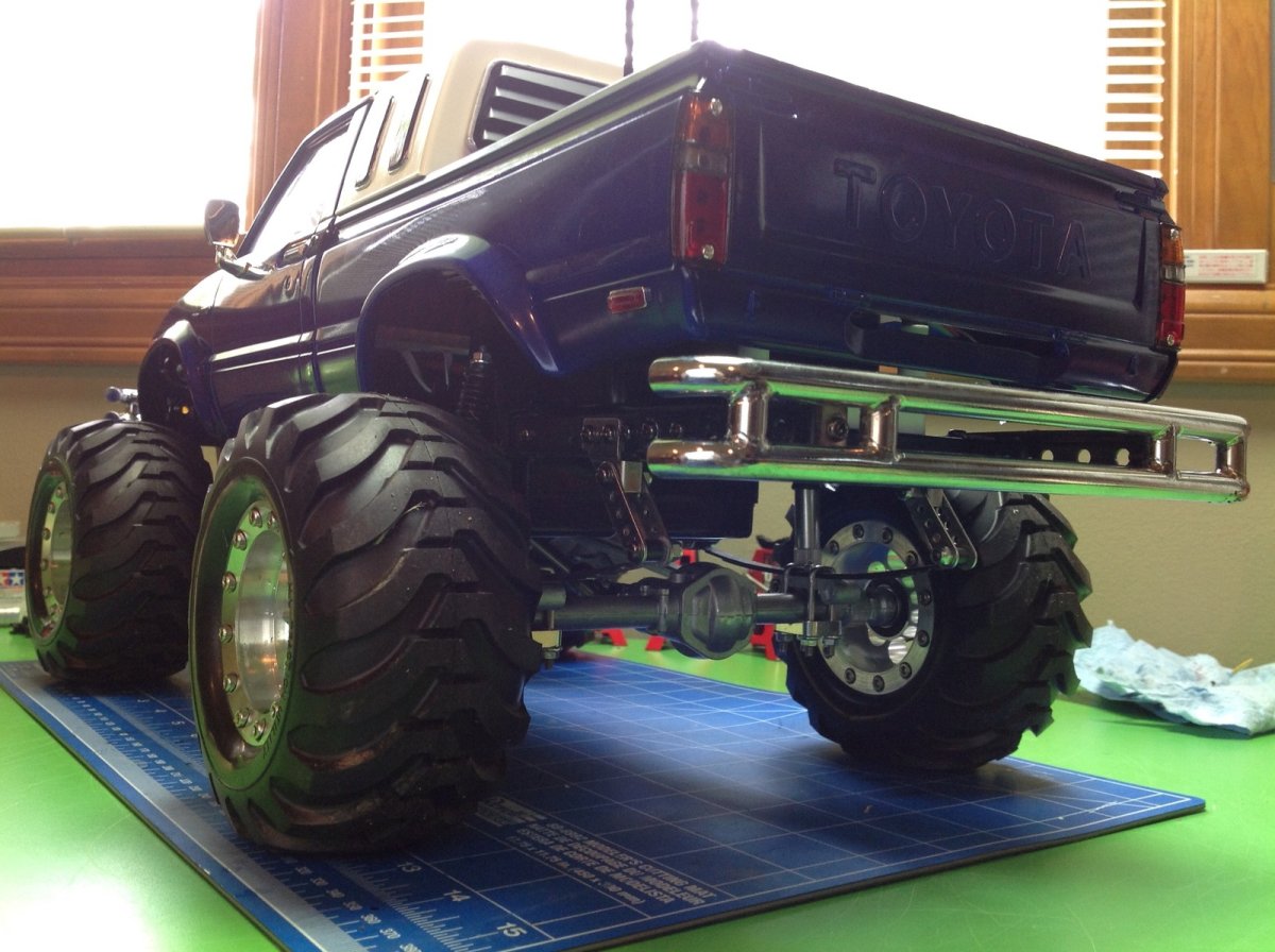
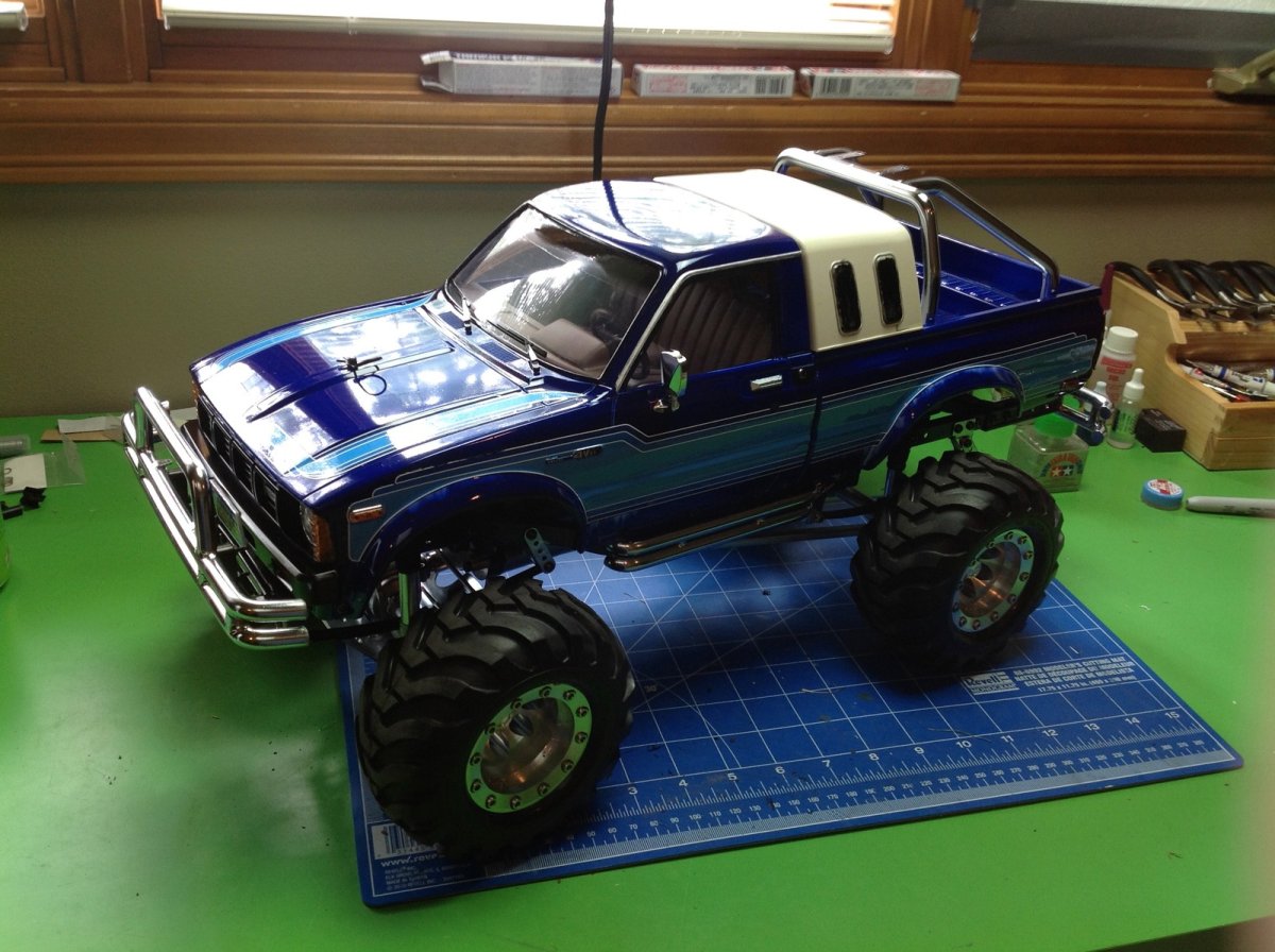
Here are a few photos of the completed Bruiser. Click each for a much larger version. Note that I hadn't made some of the final upgrades when these photos were taken.
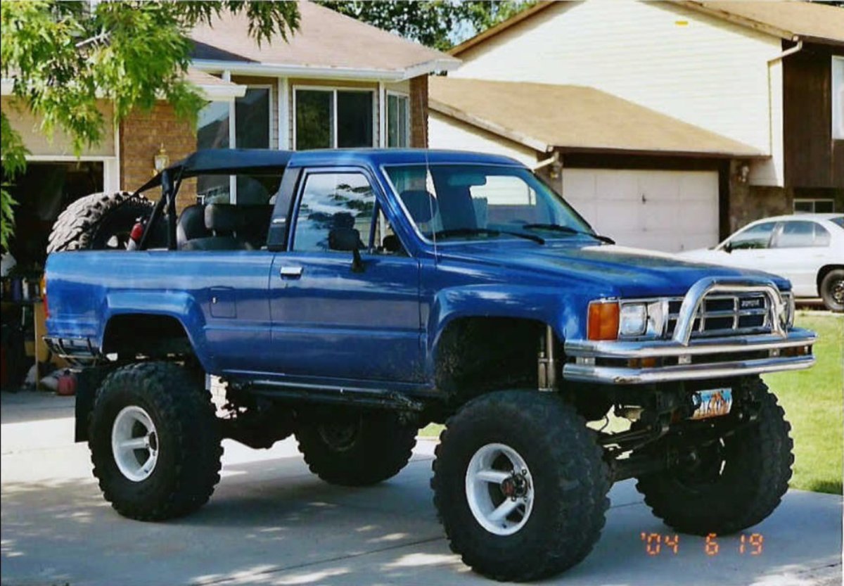
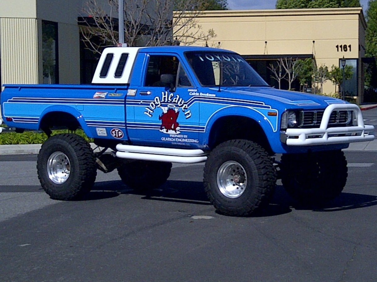
Here are a couple of pictures of the real thing. The first photo shows a Toyota truck configured much like a Bruiser in the wild. I have no idea if it was intentional. The second, on the other hand, was intentional. They even copied all of the stickers from the model and it looks amazing.
_____________________________
Written by Eric Albrecht
Visit Eric's personal site with lots of build threads.