

The weak point of the Cheetah 58007 and FMC XR311 58004 models are the torsion bars of the front and rear suspension: 4 black plastic bars. It is virtually impossible to find new ones.
The XR311 re-released in the early 2000s has metal torsion bars that cannot be used with the original model unless the suspension arms and the bar torsion adjustment pawl are changed. So when the originals are broken there is only one viable option, rebuild the damaged part.
Preparations
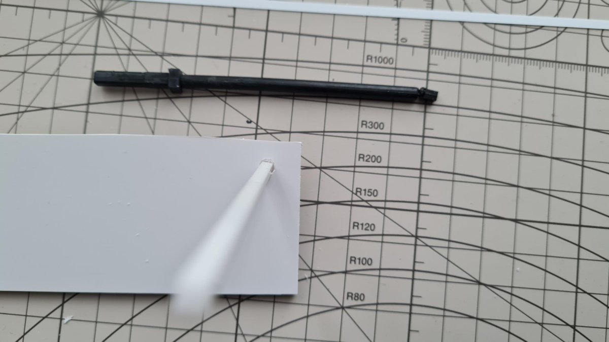
It is highly likely that the torsion bar has snapped with broken square pin stuck inside the suspension arm.
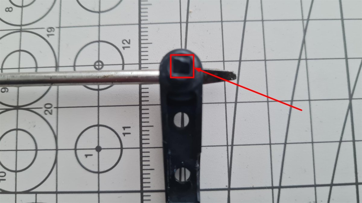
The arrow highlights the square pin stuck inside its housing in the suspension A-arm. As is often the case, the damaged square pin cannot be pulled out of its housing even using small pliers.
To remove the square pin do as follows:
- Prepare a paper clip or a piece of 1,5 to 2mm diameter metal wire.
- Heat the wire of the paperclip using open flame.
- When it turns red, immerse the wire into the square pin stuck in its housing. Be careful not to damage the housing and not to go too deep.
- Hold the paper clip in place as long as necessary for the melted plastic to solidify.
- When the plastic is solid again, pull the damaged part out by pulling the paper clip

The square pin still welded with the paperclip that has been removed from its housing
Repairing the torsion bar
The length of the XR311 torsion bars should be between 99 and 100 mm long. The rear torsion bars of the Cheetah are the same length while the fronts are 10 mm shorter due to the shorter wheelbase.

Materials
The original material was plastic so the natural solution is to construct the replacement with styrene, which allows acetone or styrene glue to be used to weld the parts togehter.
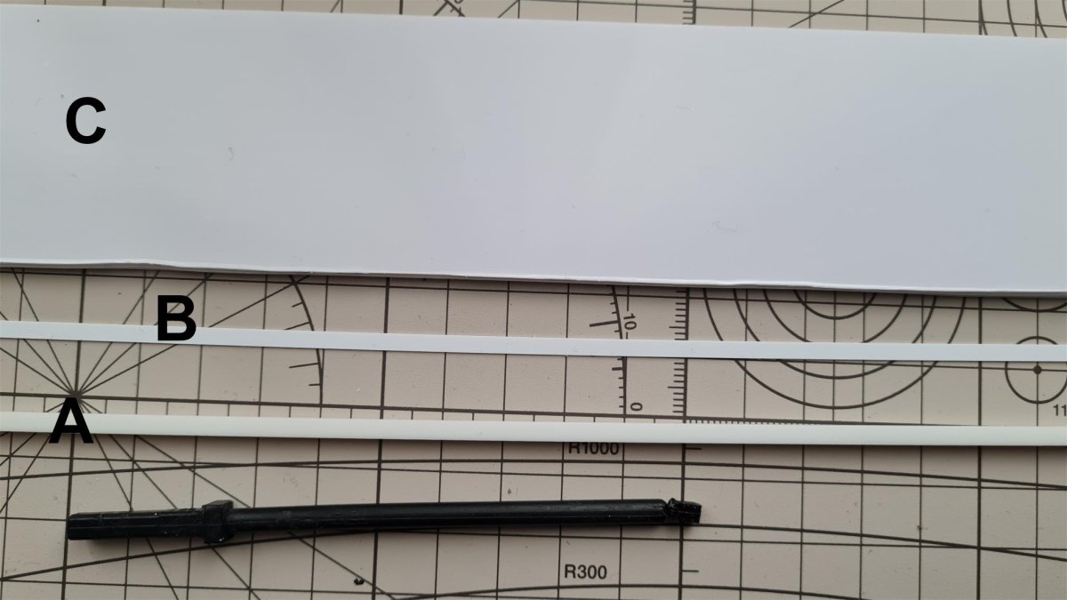
This is what you need:
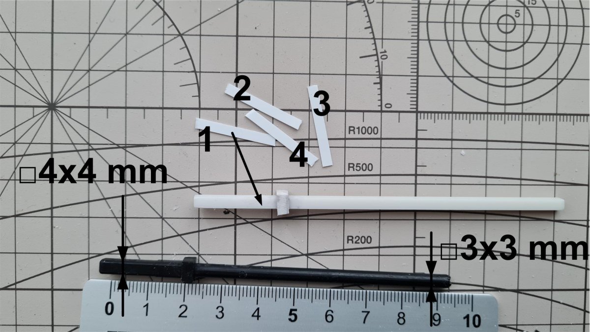
- 3mm square section bar in styrene.
- 0.3mm x 3mm strip in styrene
- 3mm thick styrene sheet
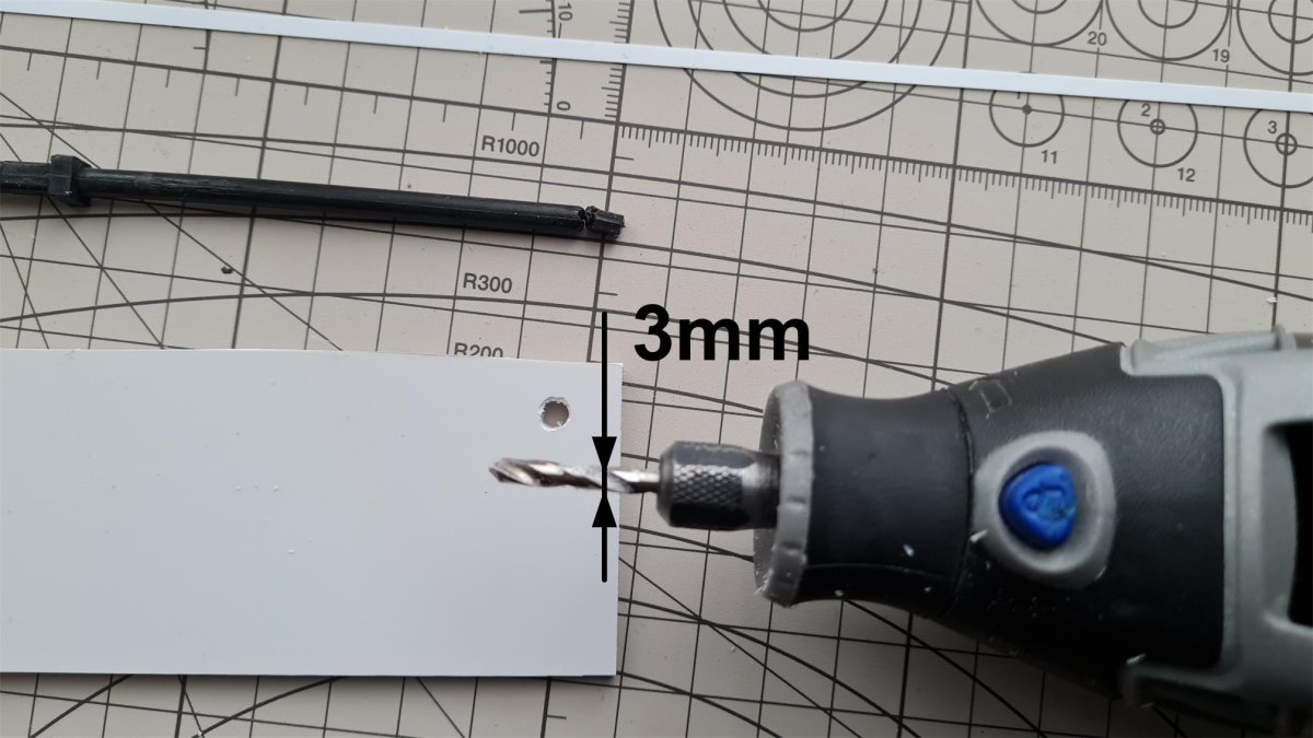
Cut out a 100mm long strip from the 3mm square section bar.

Crate a square section to replicate the part highlighted in the figure on the original torsion bar. Drill a 3mm hole through the 3mm thick sheet of styrene.
Check that the 3mm square bar fits perfectly into the hole, it must fit snugly to make mechanical grip.
Cut out the square with the previously made hole in the center. With sandpaper, reduce the size to the desired size from A size to B size. Final size is not too important as the square is just a spring retainer.

Use acetone or glue to attach the drilled square at the correct distance to one end of the 100 mm bar
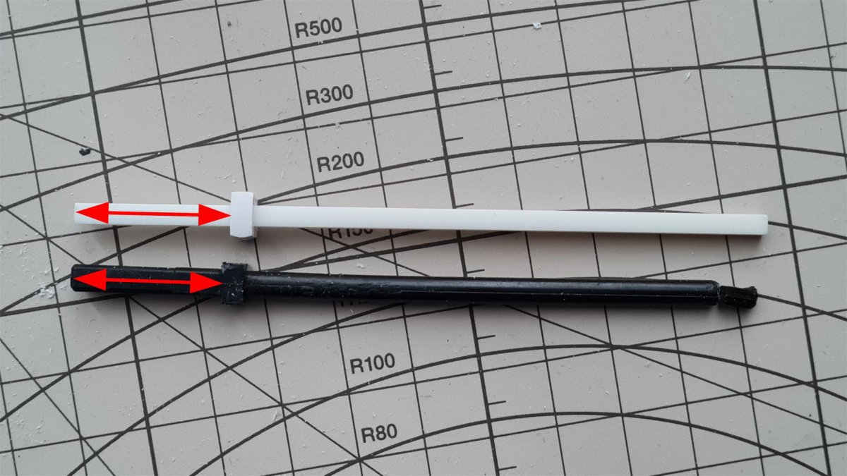
The original bar has different dimensions in the ends:
- 3 x 3mm for the square that clamps onto the suspension arm and
- 4 x 4mm for the square that locks into the suspension calibration pawl at the opposite end.
Prepare 4 styrene tabs from the 0.3 x 3mm strip. These pieces are used to enlarge the end-section of the new bar.
Glue the strips onto the new bar., creating the 4x4mm end. One strip is glued to each side.
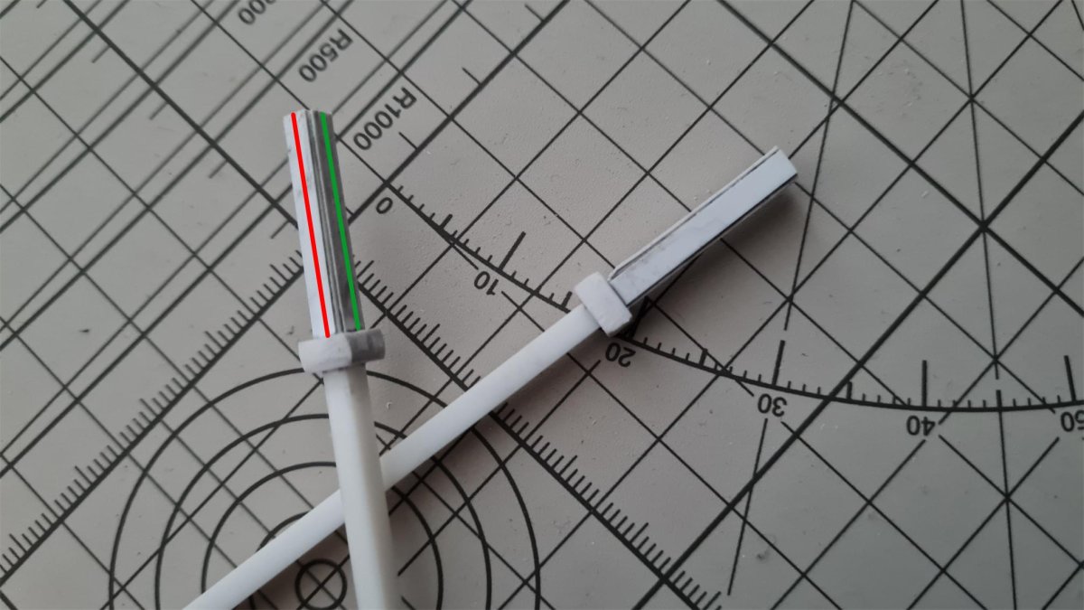
There must be no play between the new bar and the pawl; weld two strips of styrene 0,3 x 3 mm each on two different, but contiguous sides (red and green lines) to reduce the play between the parts as much as possible. Weld on the side indicated with the green line and the red line.
Using sandpaper, file the 4 mm end to remove the burrs of the 0.3 x 3 mm tabs.
Test installation
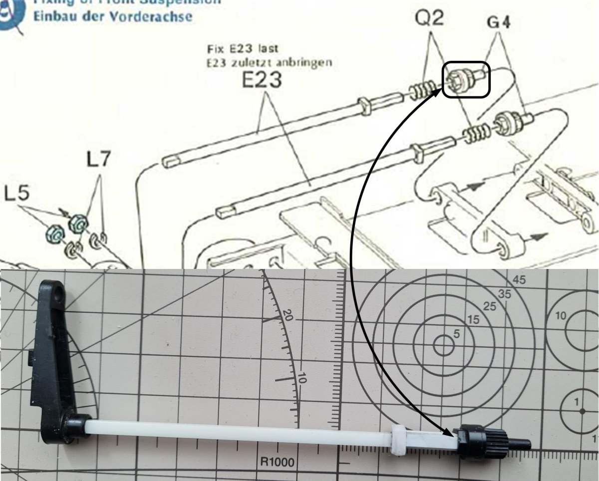
Make sure the original black parts have no play in relation to the white torsion bar. The picture shows the pawl for managing the torsion bars' tension.
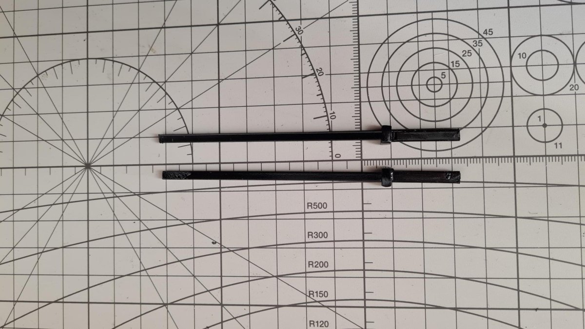
Next, you can primer and paint the torsion bars as you like, here painted black. (TS82)
Adjustments
To be able to adjust the torsion of the bars, Tamiya came up with an ingenious yet simple system.
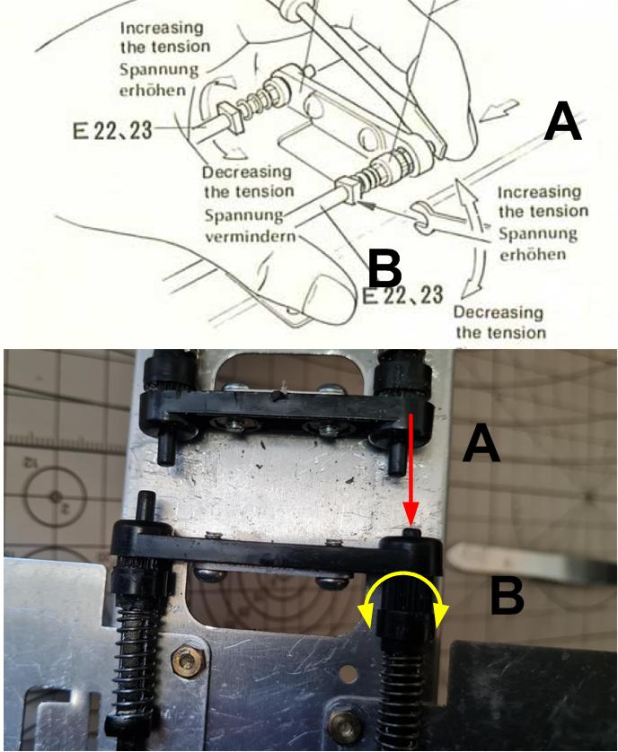
First you press the pawl towards the spring, releasing the splines from the seat (A). The seat is the plastic plate attached to the metal chassis. When the pawl is fully pressed down, turn it clockwise or counter-clockwise to stiffen or loosen the suspension (B).
Check that the new torsion bar is the right length, if it is too long the rows of the pawl do not come out of the plastic base fixed to the frame and cannot rotate for adjustment. Reduce the length of the bar using sandpaper until the torsion adjustment pawl can be rotated when pressed in the direction of the arrow.
_____________________________
Written by Gabriele Andreoni