


Introduction
At less than 25 GBP posted for a 6 channel stick radio and receiver, you've really got to ask whether it's a question of "buy cheap, buy twice", or a genuine bargain?
Unboxing
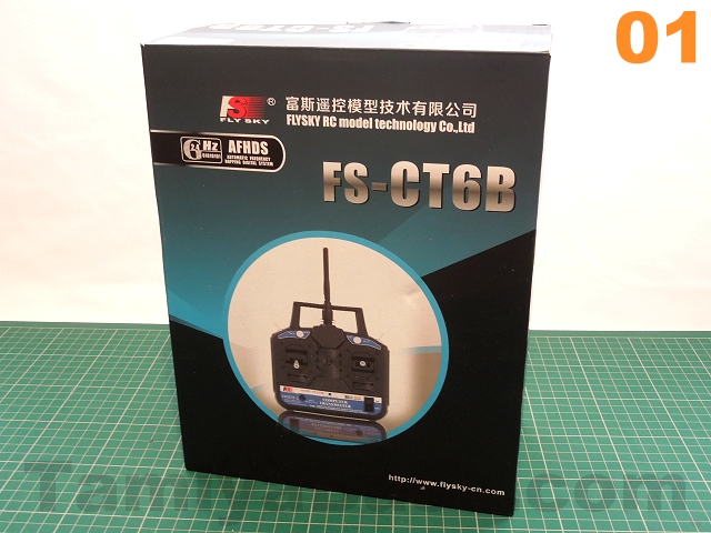
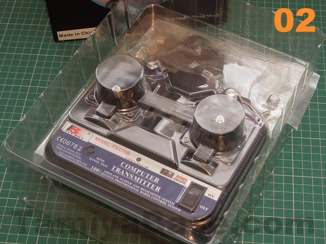
The last time I bought a real "budget" 2.4 set (the RadioLink T4EU) it didn't have proper retail packaging, just polystyrene foam forms that you'd usually refer to as "inserts" - so a full colour printed, satin feel box this time (image 01) was a pleasant surprise. Opening it revealed a clear vacformed insert (image 02) that unfolds to let you get at the contents - the FS-CT6B TX, separately bagged FS-R6B RX, binding plug, mini CD-ROM - and a surprise at this price point (though it actually turns out to be a necessity) - a USB cable with DIN plug to connect the transmitter to a Windows based PC.
You'd expect there to be some sort of manual, so that must be on the CD, right? Not so - but I did track down a PDF of one on the Hobbyking website easily enough.
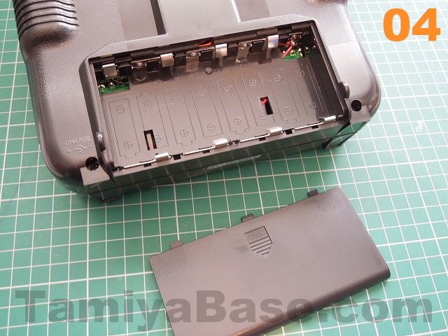
The transmitter (image 03), which I'd feared would look and feel a bit cheap actually feels reasonably solid in the hand, and weighs in at just over 500g (1lb 2oz) without the batteries. Whereas some 2.4 sets use only four AA cells, this takes a more traditional eight (image 04).

The design is a little uninspiring - though I can live with that for the price - but I do find the "COMPUTER TRANSMITTER" legend on the front panel particularly naff.
What is of more genuine concern (having short fingers) is that the stick lengths and throws are a little uncomfortable - and the end of the sticks are very rough. As soon as it was apparent that the set wouldn't have to go back as DOA, I smoothed them down a bit with wet & dry paper.
Features
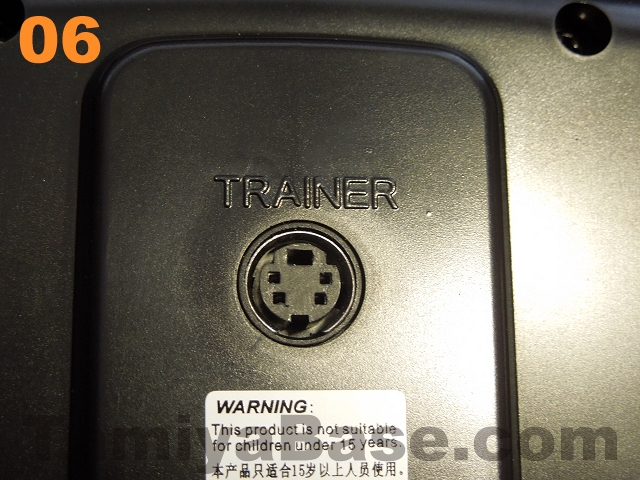
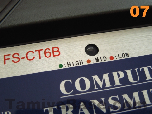
The 2.4 GHz antenna is pretty standard fare, folding 90 degrees (via a 45 degree intermediate step) for storage, there's a moulded in lanyard attachment point, a charging socket on the right lower corner (image 05), DIN "TRAINER" socket on the back (image 06 - also used to connect to a PC), and, on the printed front panel, a binding button (also labelled RANGE TEST, which I haven't got to the bottom of yet), an on/off switch, and a power indicator. The latter has a nice touch (which I've also seen on other sort of electronics over the last couple of) - it changes from green to orange to red as the battery charge runs down (image 07).

The sticks are as you'd expect for a flight TX - the right stick is free and sprung in both directions, whereas the left is free/self centring on the left right axis, but lightly ratcheted and unsprung in the vertical plane. Trim tabs are the traditional ratcheted type for all axes.
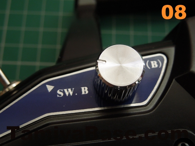
The remaining controls are two rotary potentiometers labelled VR (B) and VR (A) which turn approximately 270 degrees (from around 10 o' clock to roughly 8 o' clock), and two small switches labelled SW.B and SW.A (see image 08 - right side is a mirror image).
Something I didn't immediately notice was the lack of reversing switches on the transmitter - I'll cover that later.

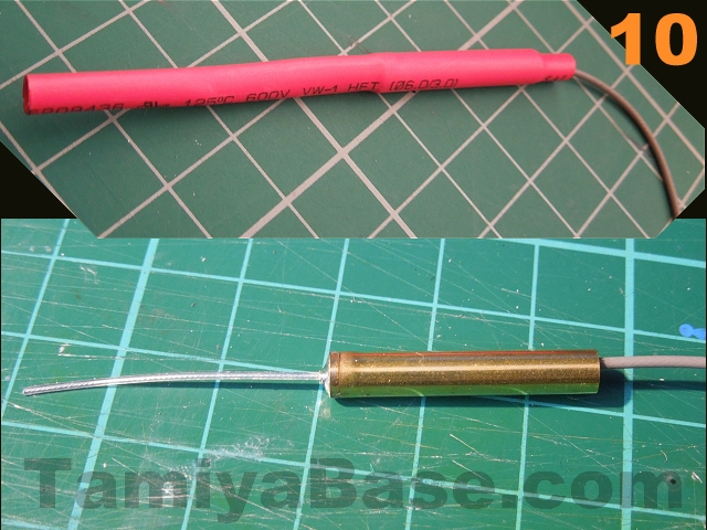
There's not much to say about the receiver (image 09) - it's fairly small, doesn't appear to have BEC (battery eliminator circuitry) so would probably fry if connected to an older Tamiya ESC, and there's no bind button (hence the binding plug). I wasn't sure what was going on with the antenna as half of its length was hidden by heatshrink tubing, so sliced it open to have a look ... I'm not clear what the point of the soldered on brass tube is (shielding of some sort, no doubt) as I haven't seen such a thing on a 2.4ghz receiver before (image 10).
I've seen this TX sometimes described as having a multi model memory (i.e. the same transmitter can switch between several different vehicles) - but that is WRONG. ... Well, sort of. If you connect the TX up to a Windows PC it's possible to have an awful lot of settings saved to your hard drive as the files are less than 4kb each - but it's not very convenient.
Binding
This is the process by which the receiver learns which transmitter it's supposed to take instructions from (and ignore all other signals) - usually it involves some sort of unique Vulcan nerve grippery, so it's good to see this is actually explained in some depth in the manual (or it would be, if the manual was provided).
The combo comes pre-bound, but for reference purposes:
• start with TX and RX turned off.
• insert bind plug in channel 6 of RX, turn RX on (note flashing LED);
• hold down bind button on TX, turn TX on, when RX LED stops flashing (around 10 seconds), process is complete - take finger off bind button on TX & remove bind plug on RX.
Initial Setup
Just what components should plug in which channel has never been particularly intuitive on radio gear, or indeed a strong point in their product manuals - but the more channels there are, the more problematic it becomes. Initially, the receiver didn't appear to have any markings indicating the correct orientation of plugs going it to it (though it's obvious in photos - see image 09, above, for example ), but luckily the rule of thumb that the negative pin is on the outside of the case, signal pin on the inside held true here.
The manual is no help at all in determining which controls affect which receiver channel, but a bit of fiddling about determined that the out of the box pinout for the RX is:
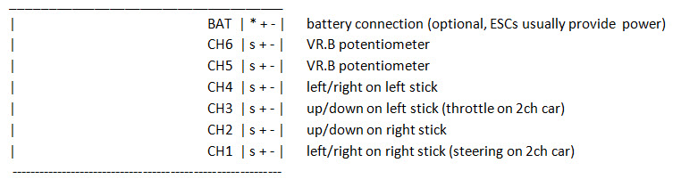
Additionally, SW.B (the upper left switch) acts as a throttle cut off in its "on" position (forward) - which might be fine on a plane, but it throws a car into full reverse. SW.A (right side) reduces the steering servo travel end points by about 50% when engaged - which seems of dubious use on a car.
The setup I want for my project is basically as for a 2 channel stick setup (so a steering servo in CH1, ESC (electronic speed control) in CH3, plus winch control on the up/down axis on the right stick, lights on off on the right switch (SW.A) and a bonnet (hood) release on the other (SW.B). The 5th/6th channels (and switch action aren't doing what I want - so it's time to install the software on the CD & see if I can do anything about that.
I'd also have to do that if any of the servos needed a change of direction - a bit of a pain as reversing switches have been the norm on transmitters since the late 1980s.
Software Setup
The CD didn't auto run, and as neither of the two files mentioned in the manual were present, I ran the only two exe files that were: t6config.exe found in the root directory and CP210xCPCInstaller.exe found in the Windows_2K_XP_S2k3_Vista directory (non Windows OSs are not supported) - then rebooted.
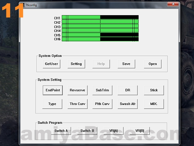
Upon restarting, the icon for the T6config app (image 11) looked the obvious thing to try, and plugging in the USB lead installed the USB to UART Bridge driver (or completed it anyway) - all looking very promising so far... but getting the plug in the back of the transmitter was an absolute pig - there's absolutely no tolerance for even a tiny error in rotation, though some might call that "positive location" ...
The manual says the first thing you should do is select the "Type" (of transmitter setup) you want under "System Setting" - note that this is not the same as "mode" - mine seemed to be set to "ACRO", and as the other options (" HELI-120", "HELI-90" and "HELI-140") seemed even less appropriate, I clicked on "CANSEL" (sic).
Before doing too much more poking around it seemed prudent to make a backup of the current settings - "Save" button under "System Option", create a folder, enter a filename, then click "Open". (Again, really).
The "EndPoint" button allows you to set how far the servo/device on each of the six channels travels in either direction - for example if you have a servo saver that strains at full lock, or even doesn't turn far enough, you could dial the EPA down (or up). Default settings are 100%, but any value between 0 (no movement) and 120% is allowed.
"Revserve" (again...) opens up a widget allowing you to check boxes for each of the 6 channels ... those boxes are labelled "NOR", does that mean that by default, all the channels are set to reverse?
"SubTrim" appears to alter the zero point of each servo (independent of the TX trim tabs I guess?) from -120 to + 120 (degrees?) from normal.
"DR" allows adjustment of dual rates for channels 1, 2 & 4, according to the manual... No, I wasn't any the wiser after that either, dual rates aren't something one tends to come across with basic 2-channel radio sets ... this (https://www.youtube.com/watch?v=skU51E5ilG0) was the first hit that came up when I Googled it, I'll watch it at some point. Note: this made more sense after investigating the switch settings later - I'm not entirely stupid, after all.
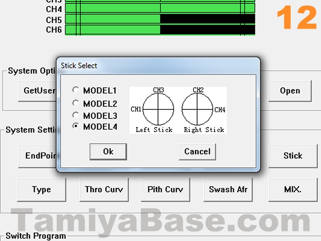
"Stick" allows you to change the "mode" of the transmitter (which axis of which stick does what) between "MODEL1" (sic), 2, 3 and 4. The diagrams that come up (image 12) would have been useful earlier ...
"Thro Curv", "Pith curv", "Swash Afr" and "MIX." don't really have any relevance to me trundling slowly around on the grass TBH, so I'll read up on them if I ever take up flying ...
... the "Switch Program" settings though initially looked very promising for getting the switches to do what I want... I had expected "Switch A" to be set to "DR" (the 50% steering servo range making more sense now) and "Switch B" to "ThroCut" (given the ESC behaviour), but both were set to "NULL"...? ...
At this point I realised the "Setting" which was on "COM1" should have been set to "COM3" - and once it was, the green/black sliders at the top of the window actually showed control positions in real time, and the switch settings as I expected them to be. However, I still can't make the switches do what I want them to do - work as simple on/off controls for lights etc - but at least with them both set to "NULL" there's no chance of hurtling off backwards or with reduced steering. I will have to live with the rotary controls acting as switches, but perhaps there's something I can do with the setup (maybe EPA?) so that a full twist isn't required each time.
I have to admit this is the first time I've used a setup quite like this, so although the software looks crude, is riddled with poor spelling, and is not wholly intuitive (at least not at first) - it does seem to give you an awful lot of adjustment options that are usually only available on much more expensive transmitters with lots of dials, switches and a costly LCD screen.
Unlike some 2.4ghz transmitters - which need to be turned off and on again to have changes to their reversing switches take effect (I'm thinking especially of the Planet T5 here) - the FS-CT6B software lets you change things in real time: while I was writing up this section (and once I'd discovered the COM setting), I had a chassis powered up & lifted off the bench, and could immediately see the effects any changes I made.
I did think that (subject to having a tame boffin with a laptop), that on the fly setup changes ("needs a bit less EPA on left turns" or "throttle curve needs more in the middle") could be made while your car was whizzing round the track ...
Modding the Left Stick
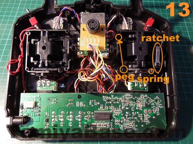
A throttle with a ratchet & no self centring really doesn't work for wheeled vehicles, so the left stick needs some fiddling with.
The ratchet is a simple metal tang that can simply be removed (or turned 180 degrees in case you ever want to change it back).
The mount points for each self centring mechanism (a tiny spring and plastic lever) are the same across both axes on both sticks so you have a couple of options: one is buying another identical combo, which will give you enough parts to modify a further 3 transmitters (as well as give you a bunch of spares - including a receiver) at not too much cost.
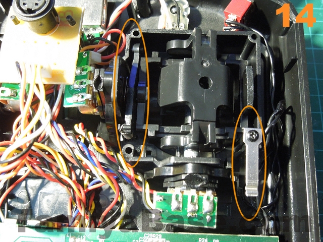
I went for a cheaper option though - swapping the centring mechanism from the left/right axis to the up/down (carefully unclip the spring from the lever, swap the lever over, unclip the spring from the lower post, and move to the other axis - small pliers & good light are all you really need). This did mean that the left/right axis became extremely floppy - so I made a quick guide for the outside (45mm disk cut from styrene sheet with compass cutters, 4.5mm slot drilled at the ends & the ends joined up with a craft knife, carbon fibre look vinyl sheet on one side, double sided tape on the other).
(See images 13, 14 and 15).

Conclusion
It'll be a long time before the project this radio is intended for will see actual driving, so out of necessity this piece is based just on a bench test (or initial poke around, if you prefer), but even so it's easy to see it has great potential.
| + | Neutral | - |
|
Surprisingly solid feel Lots of adjustment options - and in real time Very good value |
Range /interference resistance/longevity yet to be tested Rotary controls have a very wide range of movement (and don't really suit what I need them for). |
Uncomfortable sticks Switch options not all they could be Battery door falls off with a very light touch - or even just sat on the desk - you'd be well advised to tape it up Servo reversing & "model memory" very inconvenient; Absent/ poor manual Crude looking software Fiddling needed for ground based RC use. |
Overall Rating: if you need the extra channels and don't mind doing some fiddling about this is a real bargain. There's lots of room for improvement, but given the exceptionally low price, it still earns a 5 out of 6 rating.

(See our notes on rolling the dice.)
However, if you want radio gear that will go into your RC car with a minimum of fuss, there are other options that are a much better fit - though not at the same price level.
________________________
Written by TB member Jonny Retro