|
|
|
TOPIC:
Blakbird's 56003 Flakpanzer Gepard Build 1 year 11 months ago #71226
|
The Flakpanzer Gepard is not a tank. It looks a bit like one, riding around on an armored tracked chassis, but it is more rightly called a SPAAG (Self Propelled Anti-Aircraft Gun). In the case of the Gepard, an anti-aircraft turret supporting a pair of Oerlikon 35mm autocannons has been fitted to the chassis of a Leopard tank. Like the Leopard, it uses 7 pairs of road wheels on torsion bar suspension driven by a 37.4 liter, V-10 engine with twin superchargers. Unlike the Leopard, the Gepard has an additional 4-cylinder diesel engine proving electric power for the turret traverse, gun elevation, and twin radars. The rear mounted parabolic dish is for the search radar used to find targets. The front mounted tracking radar is used to guide the cannons once a target has been designated. The turret is capable of movement much faster than that used for a large bore tank cannon. Each barrel has a fire rate of 550 rounds per minute (almost 10 per second) which makes for a crazy pile of ejected casings when this thing is in use. I highly recommend finding a video of one in action and enjoying it. Incidentally, "Gepard" means "Cheetah" which puts the naming of this vehicle in line with other classic German armor using big cat names like Leopard, Tiger, and Panther. It is odd that we in the English speaking world refer to this one by the German name instead of the English translation.
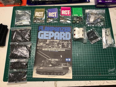
Tamiya had started their line of 1/16th scale RC tanks in 1974 with the M4 Sherman. The second model was the Leopard A4 in 1977 and then the Flakpanzer Gepard in 1978. Given that the Gepard first went into service in 1976, it was quite a new vehicle at the time the model was made. At first it made sense to me that Tamiya would make this model immediately following the Leopard A4. I figured they would just take the same chassis and hull and put a new turret on it making it very easy to develop. I was wrong about that. The Gepard is actually slightly longer than the Leopard due to some additional space between the third and fourth road wheels as well having a longer rear engine deck to make room for 6 additional 24V batteries. So although it shares features and a superficial resemblance to the Leopard model, a great many of the parts are new including the entire hull section. Tamiya also made a lot of changes to the electrical system in the one year between the Leopard and the Gepard. The Leopard used only 2 channels with no speed controller, so on/off were the only speeds. The Gepard added a continuous mechanical speed controller while maintaining the same gearbox driven by a single 540 motor with steering controlled by dual clutches. The Gepard also added a 3rd channel which simultaneously controlled turret traverse, gun elevation (through a cam system), and search radar rotation. All of these tertiary functions were powered by a separate 3V battery pack. With the 6V lead-acid pack for the motor and the 4.8V pack for the radio system, that makes 3 independent power systems used in the original model. The Gepard continued to be manufactured by Tamiya for several years and some changes were made during that time. My copy has a 1983 copyright mark on the instructions. During that time, the 6V lead-acid battery was replaced with a standard 7.2V NiCd stick pack. Additionally, the proportional MSC was replaced with a simpler discrete 3-speed MSC for some reason. I made some additional changes to my build such as replacing the MSC with a modern ESC for full proportional control which also eliminated the need for a separate battery pack for the radio system. I split the turret functions into 2 channels. The 3V battery pack still powers the search radar through a mechanical switch. I added an additional ESC for proportional control of the turret traverse and gun elevation. I ended up with quite the mess of wires. The single motor and clutch steering makes for less finesse in driving that the more modern DMD systems in later tanks, but it is still very capable and a joy to drive. Because of the age and value, I am taking it pretty easy on this model though. This was by far the oldest model I'd ever built new from the box, so I was pretty nervous about even opening it. Even though the model was released in 1978, my instructions are stamped 1983 indicating my model came from a later batch. The front of the box contains a lovely hand drawn image of the vehicle (I'm avoiding using the word tank) and of the gearbox. The picture on the right is a close-up of the gearbox image. I'll explain the inner workings of this a bit later. Notice the single 540 motor 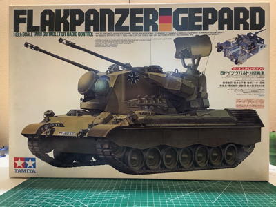
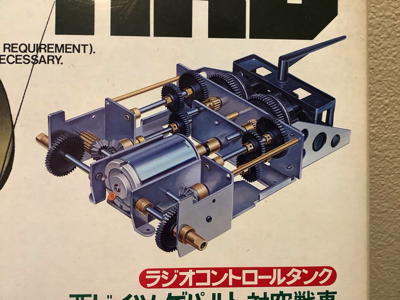
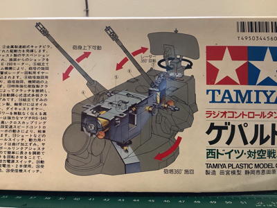
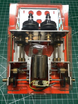
The picture on the left shows the plan view with representations of the interior components. Note that this image shows the original variable MSC and 6V lead acid battery, neither of which are actually used in my version of the model. On the right you can see an isometric cutaway of the turret. There is one motor to control the turret traverse and gun elevation (they are slaved together), and another for the search radar. 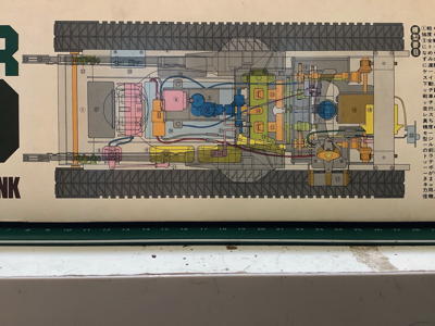
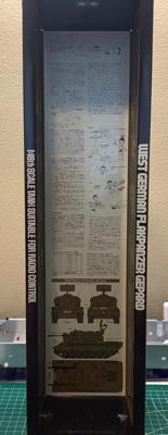
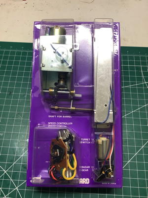
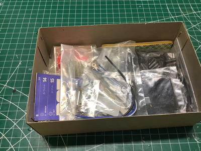
Here are some views of the inside of the box. On the left you can see the blister packs containing the important components such as the gearbox and metal suspension parts. The manual you see here is only printed in Japanese, so I had use a PDF version in English to clarify. The long slim box is shown in detail on the right and contains lots of information about the vehicle. 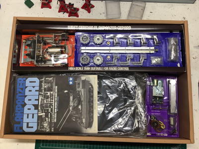
Attachments: |
|
|
Please Log in to join the conversation.
Last edit: by blakbird.
|
Blakbird's 56003 Flakpanzer Gepard Build 1 year 11 months ago #71227
|
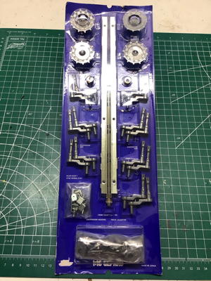
Let's take a closer look at those blister packs. On the left are the suspension arms, sprockets, brackets, and chassis stiffeners, all in metal. In the middle is the gearbox. Note that the gearbox is pre-assembled. In fact, the manual contains no instructions on how to service it. I'll be taking it apart anyway. On the right is the gearbox for the turret traverse, the radar motor, and the MSC. Note that this is a 3-position MSC and not the continuous unit shown on the box.
This box contains the hardware and other small parts including the many bits for the metal tracks. 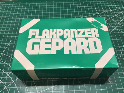
Attachments: |
|
|
Please Log in to join the conversation. |
Blakbird's 56003 Flakpanzer Gepard Build 1 year 11 months ago #71228
|
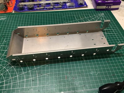
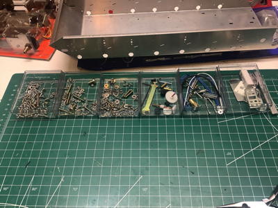
Here are the hardware bags and other bits from the small inner box. Although they are individually labeled, all need to be opened at once because the hardware is not sorted sequentially. The formed sheet metal chassis is shown on the right. Tamiya calls this "duralumin", which as far as I can tell just means aluminum.
These photos show some closer views of the hardware. On the left I've sorted the hundreds of parts used to build the tracks. On the right I've opened all the hardware bags and placed them in plastic servo cases to keep track of everything. 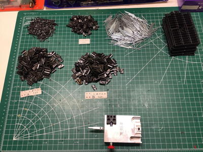
Attachments: |
|
|
Please Log in to join the conversation.
Last edit: by blakbird.
|
Blakbird's 56003 Flakpanzer Gepard Build 1 year 11 months ago #71229
|
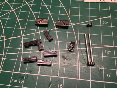
Although the manual doesn't call for the assembly of the tracks until much later in the build, I decided to start with them. I was very curious to see how the assembly process worked. On the left you can see the pile of parts which make up the tracks. The track pads, pins, connectors, and guides are all metal. The pads have an A and B mirrored tread pattern so they have to be kept separate. The only plastic parts are the spacers which sit inside the treads. There are therefore 9 parts which make up each link as shown on the right (a couple of extra plastic spacers are also shown). With 87 links for each completed track, that's 1566 parts that need to be assembled.

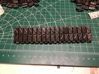
Here are a top and bottom view of a partial track assembly with 17 links completed. The pins are a slight interference fit into the connectors, so each needs to be pounded into place with a hammer. The process is slow and laborious. 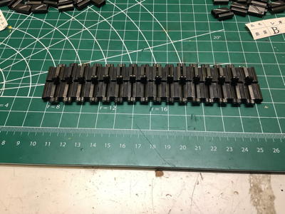
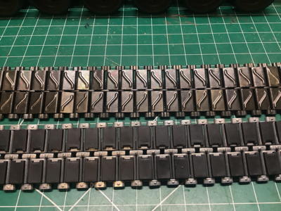
After many many hours of work, here are the completed tracks. The metal construction really gives them a satisfying weight. I found that they tended to bind and not rotate very freely on the pins. I found that the holes in the guides were not perfectly parallel because the sheet metal ends were not quite folded flush. I went through every single guide individually and squeezed the ends with a pliers to flatten them. This completely solved the issue. 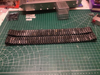
Although the completed metal tracks are lovely, I found out later through some additional research that they are also completely wrong for this tank. Apparently Tamiya just recycled the metal track parts from the earlier M4 Sherman. The Gepard is descended from the Leopard and should have tracks with rubber pads. I was able to find a set of such tracks from an aftermarket company. They are shown on the left coiled as I received them. The picture on the right compares them with the tracks that came in the box, and you can see that they are quite different. Since my copy of the Sherman didn't come with metal tracks, I was able to take the old tracks from the Gepard and retrofit them onto the Sherman. Everybody wins. 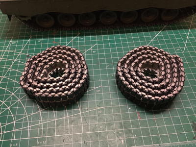
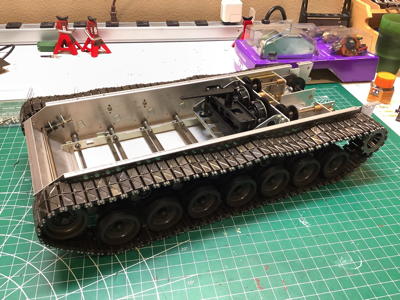
Changing out the tracks after the model is complete is not actually that easy. It required a significant teardown. This picture shows the updated and scale accurate tracks installed on the Gepard. The only issue now is that the color of the metal clearly identifies them as aluminum, but the real vehicle would obviously use steel. I can't really paint them since the rubber pads are bonded on. I guess I should just get them really dirty. 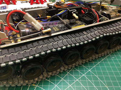
Attachments:
The following user(s) Liked this: stingray-63, Lemsko
|
|
|
Please Log in to join the conversation. |
Blakbird's 56003 Flakpanzer Gepard Build 1 year 11 months ago #71230
|
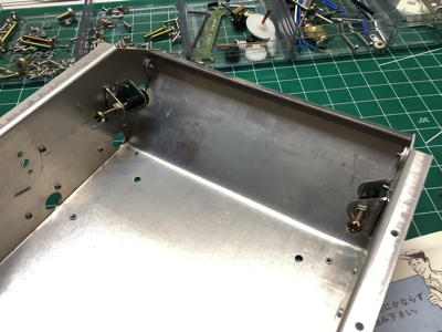
Here is the formed aluminum sheet metal chassis which forms the backbone of the tank assembly. The picture on the right shows a pair of brackets which support adjusting screws. These screws will be used to push the front axle forward which will serve to tension the tracks using the front sprockets.

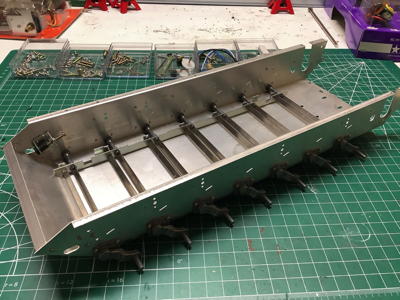
These cast parts are the suspension trailing arms. The slot on the inner end connects to the rectangular torsion bar (a simple steel plate) shown which supports the weight of the vehicle and allows articulation over obstacles and terrain features. The serrations you see on the spindles are all that holds the road wheels on. A flexible rubber bushing will be pushed over these serrations and act both as a wheel bearing and a retainer. The picture on the right shows the seven arms installed on one side of the chassis. Each has a bump stop which limits the maximum possible travel. 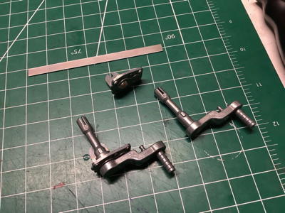
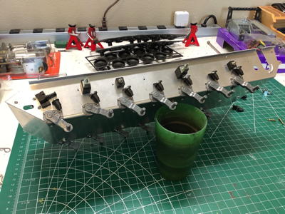
These pictures show how the torsion bars work. The picture on the left shows the brackets bolted to the chassis which serve as end locks for the torsion bars. The torsion bars insert into the X-shaped recesses. The reason they are X-shaped is so the same part can be used on both sides. The right hand picture shows all of the torsion bars installed. Note that the left and right side are offset slightly in the longitudinal direction. 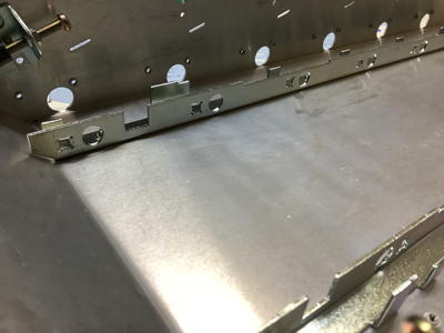
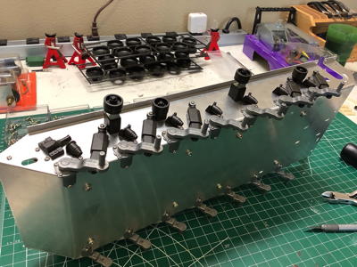
Here we see the parts that make up the faux shock absorbers. These are just for show since the piston just slides freely within the cylinder. On the real tank these would be filled with fluid and act as dampers. On the right you can see the installed dampers as well as the 4 return rollers. 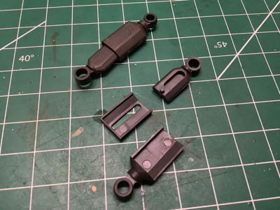
Attachments:
The following user(s) Liked this: stingray-63, Lemsko
|
|
|
Please Log in to join the conversation. |
Blakbird's 56003 Flakpanzer Gepard Build 1 year 11 months ago #71231
|
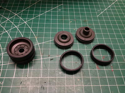
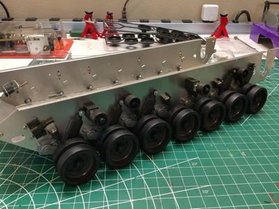
Here are the parts to build a road wheel. Each of the seven road wheels per side is actually made up of dual wheels with a gap between for the track guide. Each is comprised of two wheels and two rubber tires as shown. The picture on the right shows the completed suspension. The chassis can now roll freely.
Attachments: |
|
|
Please Log in to join the conversation.
Last edit: by blakbird.
|
Blakbird's 56003 Flakpanzer Gepard Build 1 year 11 months ago #71232
|
Tanks build is always nice to see.
|
|
Please Log in to join the conversation. |

Blakbird's 56003 Flakpanzer Gepard Build 1 year 11 months ago #71242
|
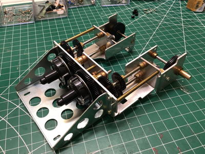
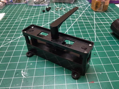
The gearbox comes out of the packaging already built as shown. There are several interesting things to note. The right and left side gear trains are mirrored but otherwise identical. The two black spur gears mate together making them rotate in opposite directions. The gears range from molded plastic to sintered metal to machined brass. Most of the gear pairs match brass to plastic with the exception of the bevel gears which are both metal (I hesitate to use the word steel). The motor input location can be seen in the right hand picture circled in green. There are no bearings in this gearbox. In general, the gears are locked to the shafts with set screws so that the shafts rotate with the gears. The shafts fit into brass bushings pressed into the sheet metal housing. All of these sliding joints need to be lightly lubricated for the gearbox to run smoothly. It is not tolerant of dirt and grit getting into it. Axial motion of the shafts is prevented with brass collars and cork washers. There are five total gear stages which progress as described below:

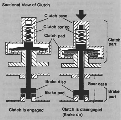
I didn't tear down the entire gearbox, but I was compelled to take apart the clutch and see how it worked. An exploded view of the parts is shown on the left and a cross section from the Leopard A4 manual (which uses the same gearbox) is shown on the right. The large black gear is the spur gear which is driven by the motor directly from the pinion so it is always spinning. I've circled the areas which are the key to the whole thing working. You may have to zoom in on the picture on the left to see the flat spot on the brass collar and on the metal disc that I'll call the rotor. The flat spot makes these rotate together. The rotor has radial grooves on it to help it grip the cork stators. When the spring is engaged (which is the default), the rotor is locked between the cork stators which are in turn locked to the annular metal plates on either side. Pressing the metal button at the end of the clutch housing compresses the spring as the housing slides aft. This releases the clutch by disconnecting the spur gear from the shaft. This is a really clever system which allows a single motor to drive both tracks while disengaging either side with the clutch for steering. Note that the clutch can be partially slipped which allows gentle turning. Zero turn radius (tracks turning in opposite direction) is not possible with this system though. One last little detail relates to the brake shown on the bottom right. Simply releasing one side would disconnect that track from the motor, but it would still be able to freewheel which would not be enough to allow for sharp turning. The whole shaft slides back when the clutch housing is pressed which grounds the shaft to the gearbox housing effectively forcing it to stop. There was a lot of engineering put into this gearbox. Not bad for a guy who had only recently transferred from the accounting department. 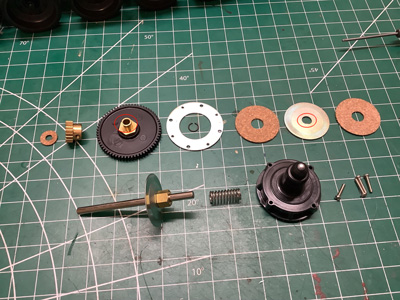
This view shows how the motor pinion drives the clutch gears. The left hand gear is driven directly while the right hand gear is driven from the left. 
This little mechanism converts servo motion into steering controls. Those old servos didn't have much torque so it was important for this mechanism to offer a lot of mechanical advantage. The very long crank arm shown on the right is driven by the servo horn. This crank rotates the square drive socket shown on the left. This socket presses the left or right cam backward. These cams contact the buttons at the end of the mechanical clutches, disengaging them. 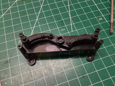
Attachments:
The following user(s) Liked this: stingray-63
|
|
|
Please Log in to join the conversation.
Last edit: by blakbird.
|
Blakbird's 56003 Flakpanzer Gepard Build 1 year 11 months ago #71243
|
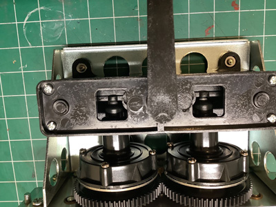
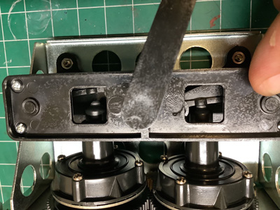
This is a close-up view showing the operation of the steering system. The picture on the left shows the system at neutral with both clutches engaged. The gap between the cams and the clutch buttons can be seen through the square windows and must be calibrated to be as small as possible. There should be no drag when driving straight, but very little servo motion should be required to engage the system. The picture on the right shows a right hand turn. The square window on the right shows the cam pressing on the clutch and disengaging it. This is a contact point with relative motion so it would eventually wear out if driven often.
Now the gearbox has been installed into the chassis. The only protruding areas are the shafts which will connect to the drive sprockets. 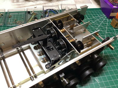
The motor is mated to the gearbox only after the gearbox has been installed into the chassis. The vintage silver can motor is shown on the left. The slotted metal collar on the motor drives an identical collar on the gearbox through a plastic key. The tabs on the key are rotated 90 degrees on one side compared to the other. This allows the key to slide on two axes so that the joint can take up any misalignment between the motor and the gearbox as the motor spins. The misalignment is visually noticeable and this system seems to compensate very well. Note that the motor is wired through a switch on the back panel. This is not really needed for the RC version, but if you wired it to simply drive straight ahead then this would be the power switch. 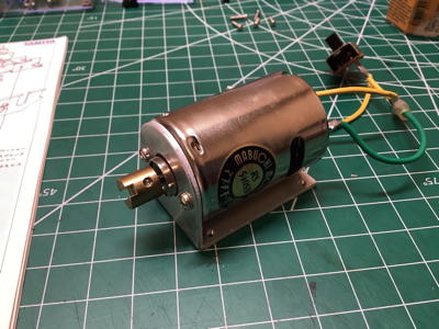

Now the tracks can be fit to the chassis. On the left you can see how the idler sprocket spins freely on a brass bushing on the front axle. Again, note that there are no bearings anywhere on this model. The front axle can be adjusted forward or back to tension the tracks. 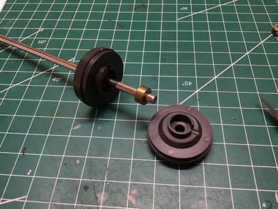
Attachments: |
|
|
Please Log in to join the conversation. |
Blakbird's 56003 Flakpanzer Gepard Build 1 year 11 months ago #71247
|
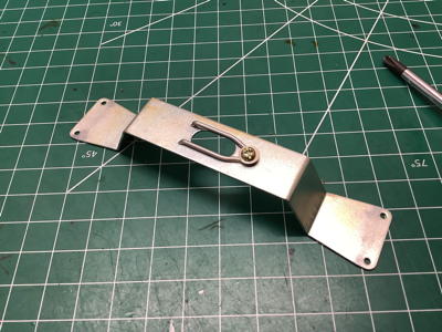
The bracket shown on the left serves as the mounting point and rotation axis for the turret. The bottom of the turret has a protrusion which fits into the slot and then rotates 1/6 turn (hex) to be retained by the spring clip. This bracket also serves as a grounding point for the turret electrical system. The picture on the right shows it mounted to the underside of the hull along with the blue ground wire.
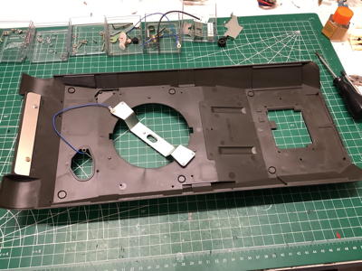
Here I've attached the large number of detail parts to the top of the hull. The real Gepard has a small diesel engine installed in the front left of the hull which is used to run generators to drive the turret traverse, gun elevation, and radar systems. The channel you see running along the left side is the exhaust system for that engine which vents through the back. The large hatch on the front left is for accessing this engine. The much larger hatch on the back is for accessing the main drive engine. The hatch on the front right is for the driver and contains the driver's periscopes as well as an extra armored panel over the hatch. The model uses this hatch to access the main power switch. 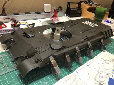
These pictures show the buildup of detail parts on the main turret housing. The picture on the left is a single molded part. On the right I've added smoke canisters, antenna supports, lift points, hatches, and periscopes. The hatch even has a clever working latch system. Everything is extremely detailed in typical Tamiya quality, though this is even more impressive given the year of release. Zoom in on the left picture and look at the weld beads and bolt heads. 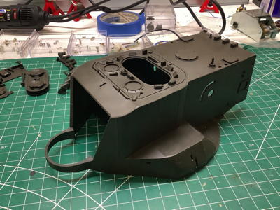

Attachments: |
|
|
Please Log in to join the conversation. |
|
|
|
Time to create page: 0.297 seconds