TOPIC:
Mod / Drag Tractor 2 years 7 months ago #68139
|
|
Please Log in to join the conversation. |


Mod / Drag Tractor 2 years 7 months ago #68140
|
|
Please Log in to join the conversation. |
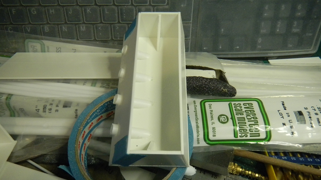
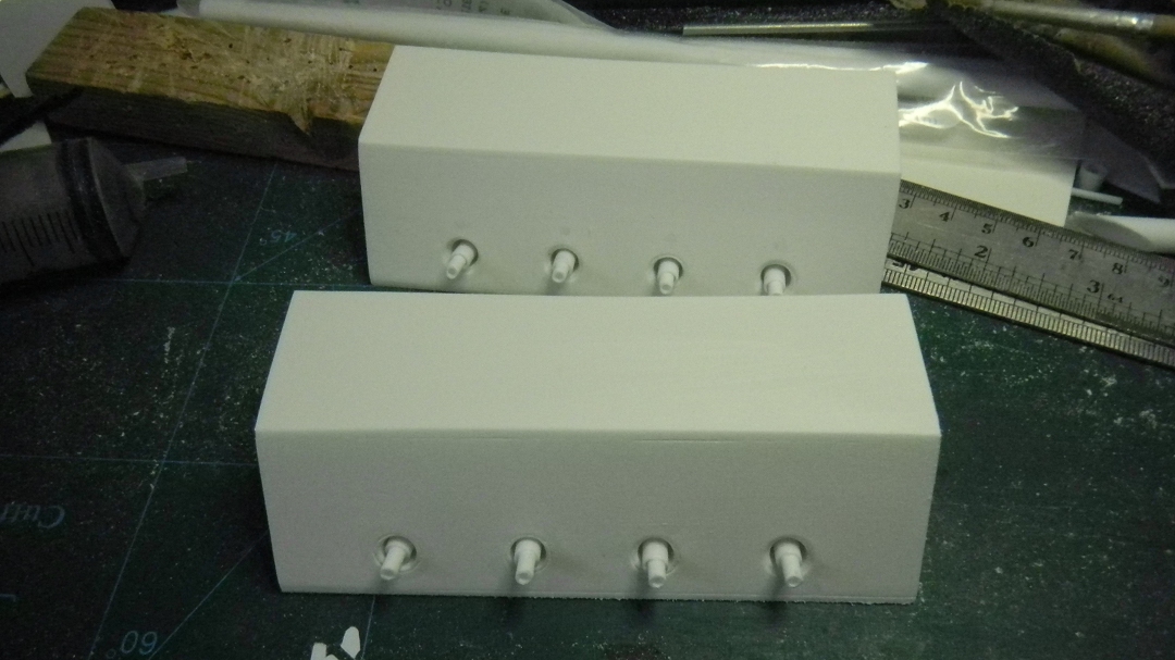
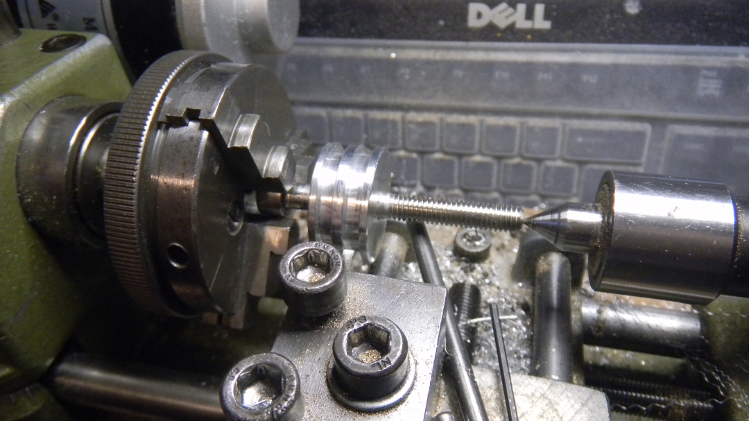
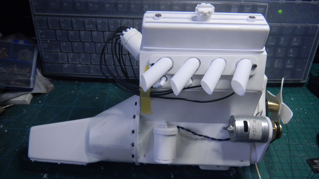
 to fill later), covers are screwed on, exhaust pipes will come later, as will the velocity stacks ... trying to think of a lighter/easier method than turning them from solid aluminium.
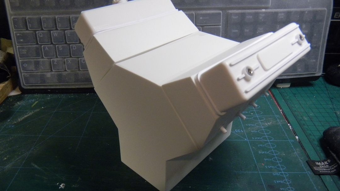
 The bodywork will need some modification ....
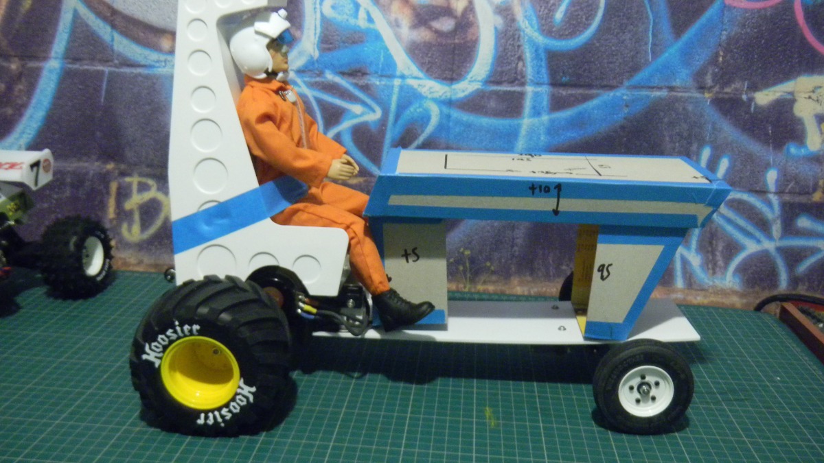
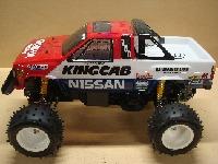
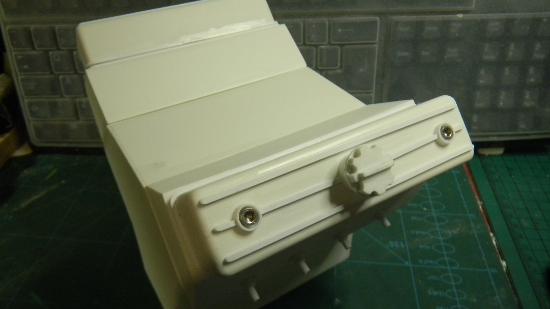


Mod / Drag Tractor 2 years 7 months ago #68162
|
|
Please Log in to join the conversation. |

Mod / Drag Tractor 2 years 7 months ago #68217
|
|
Please Log in to join the conversation. |
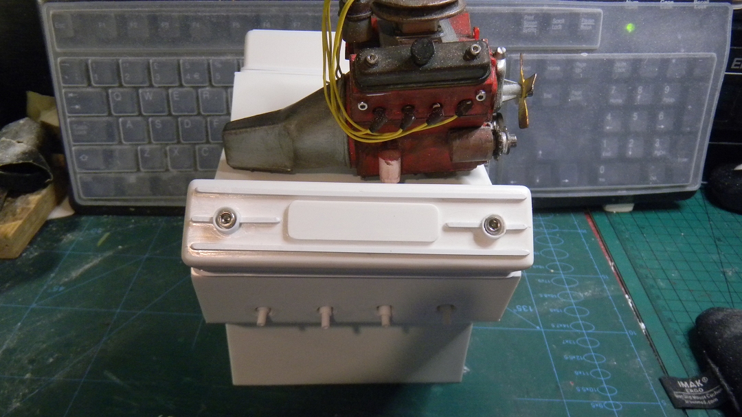
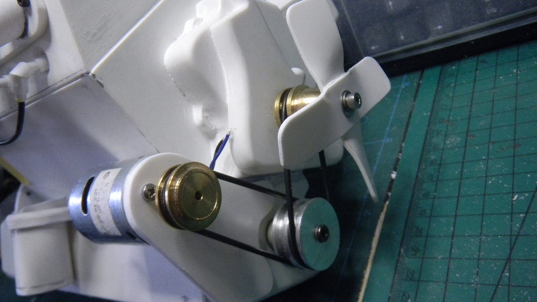
")


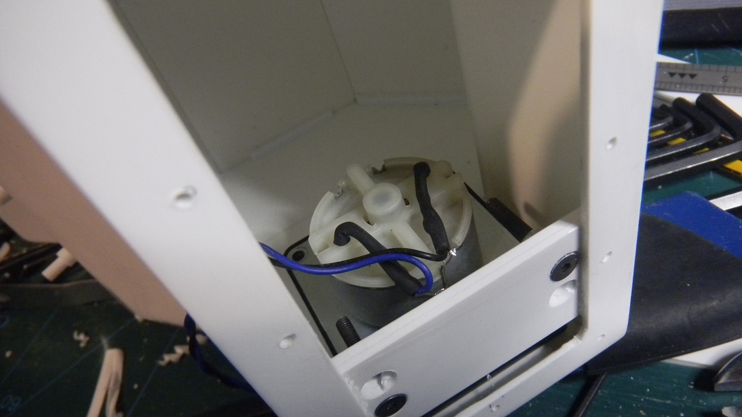
 ) & the motor barely turning.
Mod / Drag Tractor 2 years 7 months ago #68221
|
|
Please Log in to join the conversation. |

Mod / Drag Tractor 2 years 7 months ago #68222
|
|
Please Log in to join the conversation. |
Mod / Drag Tractor 2 years 7 months ago #68296
|
|
Please Log in to join the conversation. |
Mod / Drag Tractor 2 years 7 months ago #68300
|
|
Please Log in to join the conversation. |

Time to create page: 0.350 seconds