


-47350-")


-47350-")


Introduction
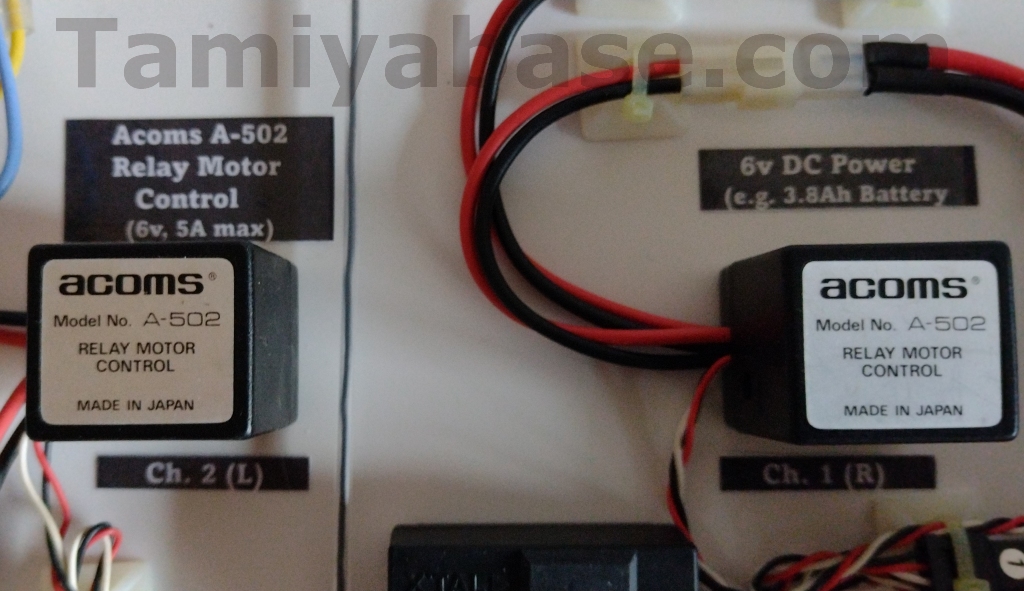
I’ve never seen an Acoms A-502 Relay Motor Control before these two came up on eBay, but the branding & the RC link piqued my interest. They were bought as used, untested, with no packaging, no manuals - and seemingly, no information anywhere on the internet.
The fact that’s there’s two of them, they’re very clean, they don’t handle much current, the size and weight, and that they only allow for simple on/off control and have the early Tamiya 6v lead acid battery connector all suggest they probably came out of a tank, but I suppose it’s possible you could have used one in a single prop plane, one or two in a boat of some sort, possibly even a hovercraft, or one of Tamiya’s gliders with the folding prop?
I don’t know if I’ll ever use these, but I would like to find out if they work – and that means finding out how they are meant to work.
Initial Investigation
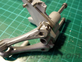
Externally poking around with a multimeter showed nothing other than continuity between the three black earth (ground, or -ve) wires. I feared the plastic case parts were glued, ultrasonically welded or permanently clipped together, but not very much torque showed there was some wiggle between them, and I was able to pull/twist them apart.
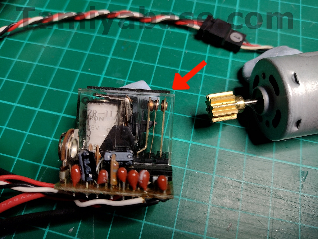
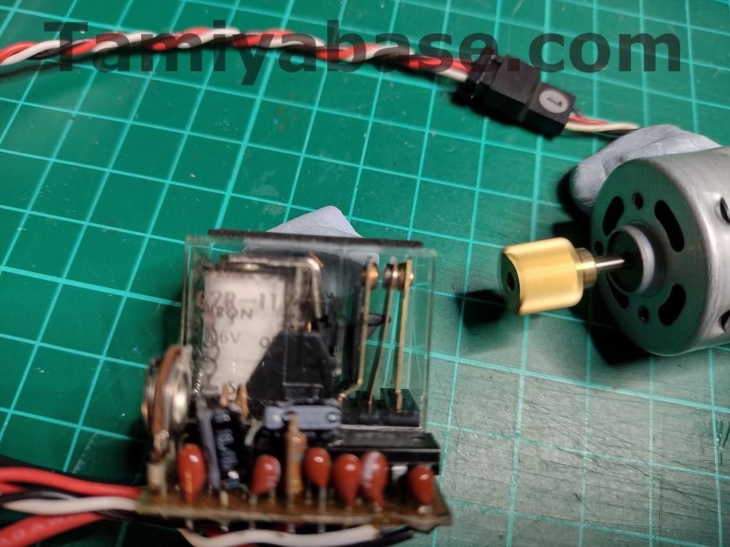
Inside I could see the most basic of 5k potentiometers (also found in early Acoms transmitters for internal setting of zero points), an Omron branded 6-volt relay (the modern equivalent of which is rated at 5 Amps), an NE544N 14-pin servo amplifier chip, various capacitors, resistors & a transistor – in other words, a relay & some circuitry to make it operable via radio control.
We already knew that from the outside, but looking at the PCB (and the diagram on the relay) allowed me to identify which of the power connectors was the “in”, and which was the “out”.
Power Connector Digression
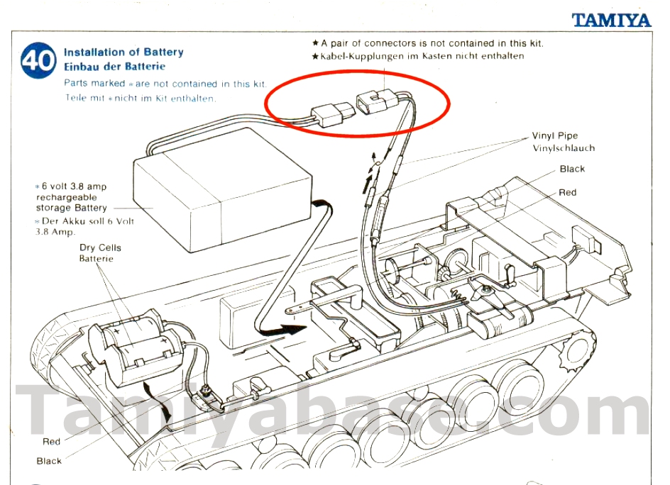
As using the right sort of connectors would make testing so much easier and safer, I wanted to get some – but as with a lot of things, that means knowing exactly the right nomenclature. Assuming the A-502 units came out of someone’s tank, I looked in some early Tamiya tank manuals. The 1974 56001 M4 Sherman showed a 6v, 3.8A rechargeable battery and the right sort of connectors – but didn’t name them, and stated they weren’t included in the kit.
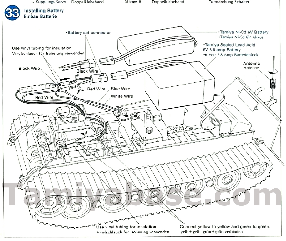
It was the same for 1977 56002 Leopard A4 and 1978 56003 Flakpanzer Gepard, but the manual for the 1981 56004 King Tiger showed that not only were Tamiya making their own 6v, 3.8A Sealed Lead Acid battery by that point, there was also the option to use a Tamiya 6v Ni-Cd battery with its own connectors (https://tamiyabase.com/parts/701-50039, now commonly known as “Graupner G2” connectors). No help there, but it did mean there was a chance that a Tamiya catalogue or RC guidebook of the period would reference that lead acid battery – and possibly the connectors.
Nb It's somewhat interesting to note that the by the time we get to 1998’s 56005 M4 Sherman manual, it’s just the conventional 7.2v “Tamiya” connector in use.
The first Tamiya RC Guide Book – 1979 – shows a Tamiya 6v Sealed Lead Acid Battery in photos of the 3 tanks available at that point, but if there was something in the text I must have missed it. The 1980 Guide Book has a basic line drawing of the battery, a wall wart charger and less than 2 column inches of description, but it’s not until we get to the end of the 1981 Guide Book that a part number (5504) is shown.
At last I had a way of finding the battery in the Tamiyabase database: https://tamiyabase.com/parts/14792-55004 . Still no answer, but I did find some pretty pictures elsewhere on the internet.
At this point, I just started Googling “old/vintage RC tank battery connector”, all possible variations, permutations and alternative phrasings - and kept coming up with nothing helpful.
I moved on to similar searches for 2-pin or 2-way auto electrical connectors, and eventually hit on a 2-Way Molex Connector Kit with .093" terminals from an auto electrical supplier on eBay – these looked promising as the nylon bits had the correct sort of “Dutch” barn-style lunchbox shape, but were clearly oversize.
Molex pins (at least for this type of connector) come in three sizes: .062” (1.57mm, 5A nominal), .084” (2.13mm) and .093” (2.36mm, nominal 8.5A), and as the blunt end of a 1.5mm drill bit fit – but not a 2mm bit, so it had to be the smallest size.
Now I knew exactly what I needed – but finding somewhere to buy them was something else, I thought I had cracked it but they turned out to be panel mount and/or latching versions. One supplier did have the right ones in a reasonable quantity, at a reasonable price, but was quoting a 9-week lead time. Another could have supplied them, possibly even next day, but with minimum order quantities, delivery charges and 20% VAT it would have been 47 GBP for 50 pairs – more than I could ever possibly use, and far too much money to try out something originally bought cheap, on a whim.
eBay provided the answer, 10 sets for just under 12 GBP, posted from a seller in Hong Kong. They looked to be ahead of schedule, but then had an unexpected week-long layover in Germany meaning they took the now-standard 3 weeks to arrive.
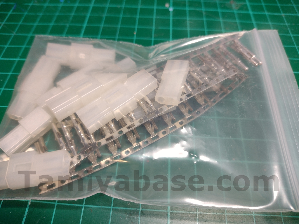
TL:DR – look for "2 pin .062" Molex Connectors".
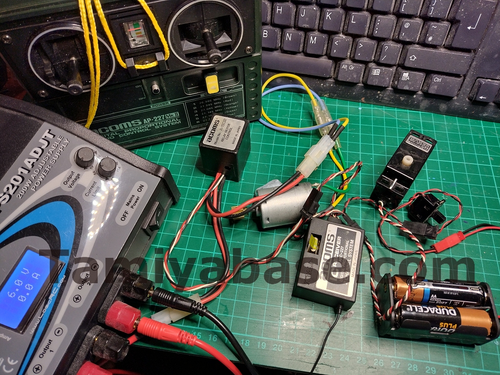
Quick Bench Testing
I wired up (crimped and soldered) a couple of the new connectors so I could try a 380 motor and my adjustable bench power supply.
As a one directional on/off motor control, I really was thinking in terms of these units being at least as early as mechanical, resistor based speed controls and that a mk.i Acoms radio (1978 on) or mk.ii set (1982) would be the right period for the A-502 Relay Motor Control, but this thinking was wrong on several counts – the connectors don’t fit the Acoms ARB receiver, and even if they did, the pinout is the more standard (earth, live, signal) order found on the mk.iii Acoms radio (with the ARC receiver) 1984 and onwards.
Additionally, the mk.iii Techniplus was the first* 2-channel Acoms stick transmitter that allowed you to rotate the gimbals from the outside, and you’d need to rotate the right stick 90 degrees to match the left on a 2-motor vehicle setup.
* and from memory, the only Acoms transmitter to offer that: the Technidrive (mk.iv) and onwards all have servo reversing switches. The mk.i and mk.ii TX gimbals can unscrewed and be rotated from the inside, I would guess that the later models have the same “feature”, but I've never had to do it ...
I tried the opened unit first, and although I could feel some buzzing there was no relay click or sign of life from the motor. Once I’d got it to work once (setting the throttle trim tab on the TX to max and giving the relay a few flicks) it worked fine afterwards.
The rheostat does as expected and is used for adjusting the point in stick travel that the relay clicks on at, and has a lot more range than is really needed – you can set it from the motor always being on, regardless of stick position, to never coming on, no matter what you do with the trim tab or how hard you jam the stick forward.
As expected, the motor control is a simple on/off (if set up correctly), with no reverse, braking or speed control.
Throttle stick in neutral, relay in off position, motor not moving:
Throttle stick forward, relay in on position, motor spinning:
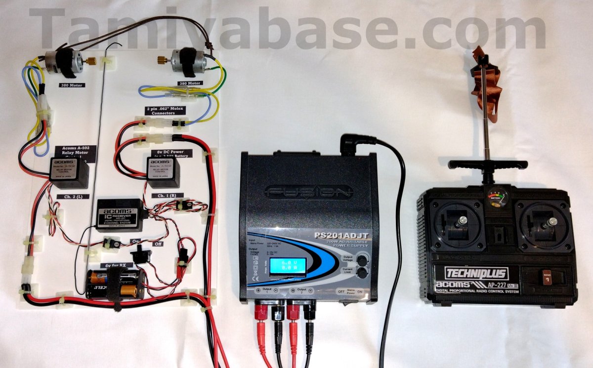
A Tidy, 2-Channel Test Rig
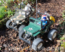
The initial test setup of missmatched radio gear sitting on the bench worked, but I really wanted to do something a little more solid – even if it meant tying up some RC components that could otherwise be usefully employed, perhaps in a vintage Grasshopper?
After cutting some slots in the 3mm styrene sheet for the motors and the 4xAA battery pack for the receiver, I sped things up a bit by using trim tape to hold the other components on, and cable ties passed through adhesive bases to tidy the wiring – I may have wanted to make a demo board, but I didn’t want to spend more than I had to.
With one motor running, the current draw as indicated on the PSU is 0.5 to 0.6A, with both it’s 1.1 to 1.2A, but it has to be note that’s with zero load. Something else to note is that an old setup like this doesn’t fail safe – turning on the receiver (with a power supply connected to the relays) before the transmitter causes the motors to spin and randomly stutter, drawing anything between 0.3 and 2.9A.
If wired in to an actual vehicle, such as a tank, you’d have a zig-zagging runaway on your hands.
Summary
It’s difficult to imagine a scenario in 1984 where a mechanical speed control wouldn’t have been better than this one directional on/off switch, the ones provided in Tamiya kits had 2 steps (e.g. all SRBs, though the Super Champ one was a different design), 3 steps the Grasshopper & countless others) or were (not quite) continuously variable (Sand Rover, etc – and the earliest tanks with a single motor & track clutches), and all had reverse. Electronic Speed Controls were very much in the minority for hobby users, but were becoming the norm for racing, being produced in factories rather than as one offs or in a tiny batch in someone’s garage.
This is probably why there’s such a dearth of examples of this sort of motor control, and so little information on them from the perspective of the average Tamiya RC fan.
That’s not to say this sort of control was a total dead end - apparently, they’re quite the thing (but with much beefier components) if you’re building a fighting robot.
__________________________
Written by TB member Jonny Retro