TOPIC:
1:18 RNLI Tyne Class Lifeboat Build 7 years 5 months ago #41539
|
Attention smart phone users - old thread resurrection; new post is on page 5
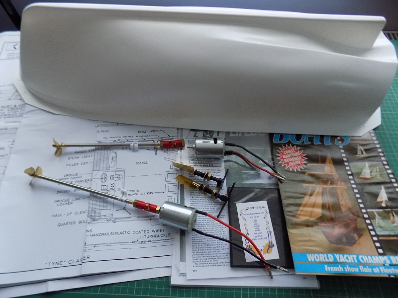
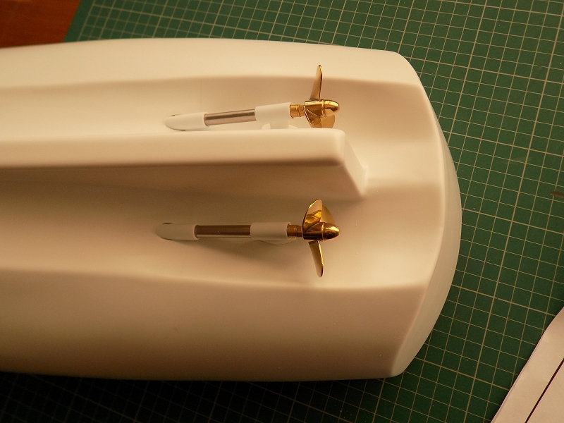
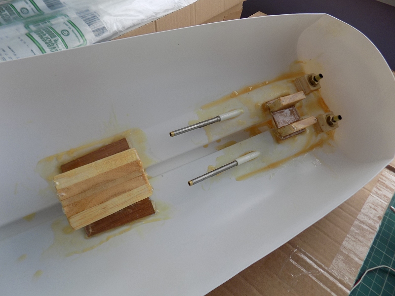
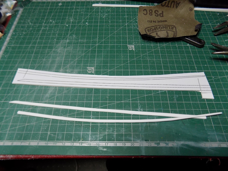
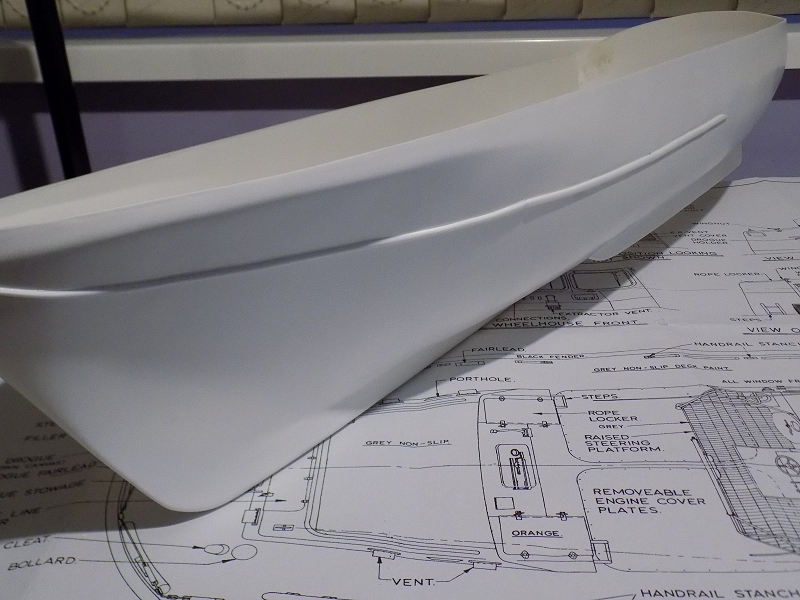
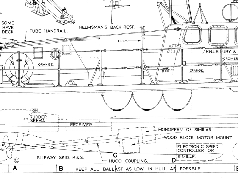
I've been wanting to build an all weather lifeboat for some time - I'd much rather have built a "taller" class (Arun, Severn, Tamar etc) as the proportions look better to me, but the cost of such kits is way out of my league. The Tyne class caught my eye as although the 1:1 boats have low superstructures (to fit in older slipway sheds), and the starting point is very (very) basic, it's comparatively cheap. Plans and a 31" vacformed hull were ordered, both showed as in stock & about a week later the hull arrived. Unfortunately, the retailer in question seems to have a "customer service" policy of giving one brush off per problem, followed by putting their head in the sand & hoping it'll go away - so my enquiries as to the whereabouts of the plans were fruitless. Luckily, model-dockyard.com sell the same plans - and actually sent them. This is only my 2nd boat build (the first being a "Kitshack" Vosper RTTL a few years ago) so I needed some clues on how to proceed. A build was documented in Model Boats Magazine in the October and November 1986, I managed to bag a water damaged copy of the latter on eBay, and scans of the first part on a CDR from Canada - which I printed out & laminated for easy future reference. Part 1 of the build article calls for a pair of "monoperm super" motors, the consensus seems to be that those were broadly equivalent to a 385 size - but in my view it's better to have too much power & throttle back (or adjust transmitter end points) than too little, so I'll be starting with a pair of 540s from my spares box. Prop shafts look to be a mere 4" (100mm) on the plans, 6.5" prop shafts were the shortest I could get in the right quantity at a price I was willing to pay, so the motors will be further forward in the hull. Assuming I keep the shafts at the same angle, the motors will also be further away from the hull - which sounds like a good thing as it's a single layer of thermoplastic ... The same source (Anglia Model Centre, mail order) also supplied rudders, prop shaft adaptors, and a pair of 40mm 3-bladed brass props - one left handed, one right. I'll sort the steering before starting on the deck, but all other electronics (a 2.4Ghz radio set driving a W-Tail Mixer & two Electronic Speed Controls) will be sourced in the future in order to spread the cost. I already have a lot of sheet, form (and scrap) styrene so I'm hoping not to spend any more there. I have a small amount of brass, no doubt that'll be something I have to fork out more for. The plans (and the build articles) are for the RNLB Ruby & Arthur Reed II as stationed at Cromer (in Norfolk) & in common with other slipway launched boats, has a white hull bottom. Looking at the other names in the Tyne class fleet, RNLB "The Famous Grouse" appeals, for the obvious reason, plus it's a red-bottomed boat - which looks better to me. I cut the hull down to the line marked (or thereabouts, in some places is was a bit wobbly) by marking with 1/8" blue 3M masking tape, then repeatedly scoring with a scalpel (10A blade), cutting vertically with aviation snips & snapping the 4 pieces off. Any remaining issues were sorted with wet & dry paper. Prop shaft hole positions were approximated as best I could from the plans, then holders cut from 5/16" tube, with the remaining parts for the skegs made from scraps of styrene. "Glue" used was bulk dichloromethane. I used Araldite epoxy to seal up the gaps & Z-Poxy Finishing Resin + fibre mat on the inside for reinforcement. Rudder tube spacers, rudder servo mount & motor mount are all balsa, reinforced/held down with more resin & fibre mat. Next, i started on the spray strips - cut from 2mm styrene sheet. |
|
Please Log in to join the conversation.
Last edit: by Jonny Retro.
|
1:18 RNLI Tyne Class Lifeboat Build 7 years 5 months ago #41540
|
Another crazy project Jonny
|
|
Please Log in to join the conversation. |
1:18 RNLI Tyne Class Lifeboat Build 7 years 5 months ago #41541
|
More catching up ... Spray rails finished:
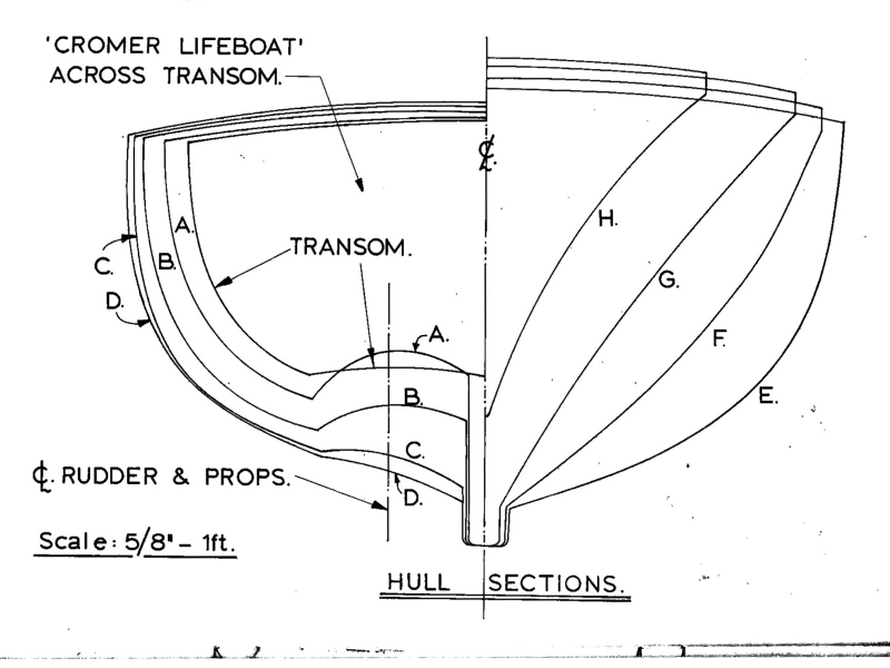
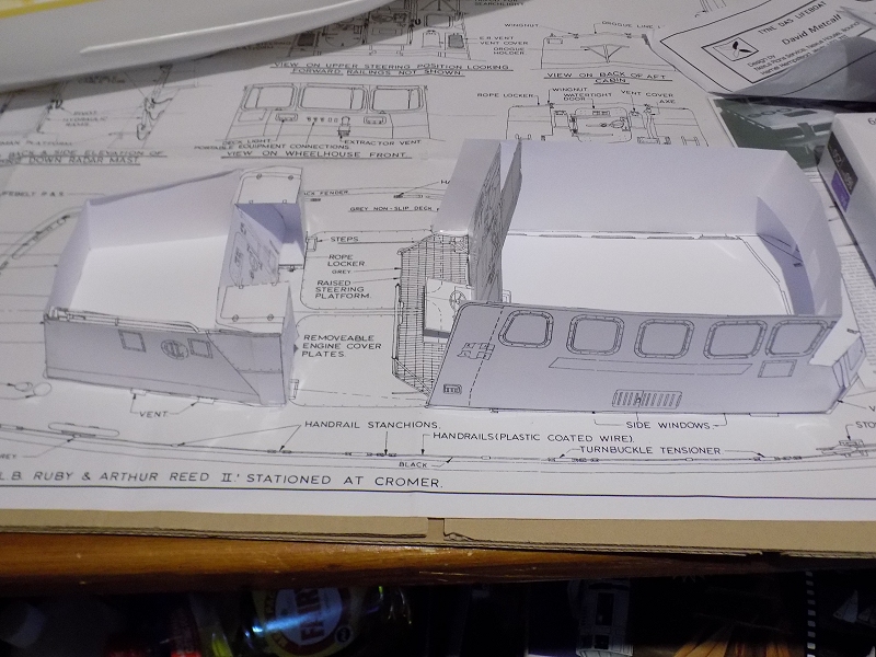
Slipway skids & tow hook... This is where it gets tricky ... and by "tricky" I mean in the context of the build so far making the Vosper "kit" look easy, so i guess I mean "impossible" ... The build article shamefully glosses over making the deck support beams, then implies that the positioning is crictical ... so there really ought to be some indication of where they go, on the plan, and on the hull? There are some end-on sections shown on the plan, and those points are shown on the side view - but they don't correspond to the makrs on the hull, or bear any relation to where the deck support beams are meant to go. The only way I can see to do it is backwards - make the deck, make the cutouts, then make the support beams. Making card mockups of the superstructure should help get the deck apertures the right shape ...
The following user(s) Liked this: stingray-63
|
|
Please Log in to join the conversation. |
1:18 RNLI Tyne Class Lifeboat Build 7 years 5 months ago #41543
|
I just have to ask, why a lifeboat?
Signature now gets correct formatting if you edit it in your Profile. Use normal BBcode if you want.
www.tamiyabase.com was formatted automatically. |
|
|
Please Log in to join the conversation. |
1:18 RNLI Tyne Class Lifeboat Build 7 years 5 months ago #41545
|
A killing project! elementary
and exciting |
|
Please Log in to join the conversation.
Last edit: by stingray-63.
|
1:18 RNLI Tyne Class Lifeboat Build 7 years 5 months ago #41624
|
Principally because of my maternal grandparents I guess - both served in the Navy during WWII, my grandmother as a WReN & my grandad's "easy time of it" (his words) included getting sunk by the Japanese (see en.wikipedia.or..._off_Endau) - both were/are lifelong financial supporters of the RNLI, so as a nipper I was always seeing newsletters, model lifeboats & so on. Plus, this is a small country & you're never that far from the coast - and a lifeboat station - domestic holidays were always to the coast somewhere & often included a look around a lifeboat station. Short answer: nostalgia.
The following user(s) Liked this: stingray-63
|
|
Please Log in to join the conversation. |
1:18 RNLI Tyne Class Lifeboat Build 7 years 5 months ago #41626
|
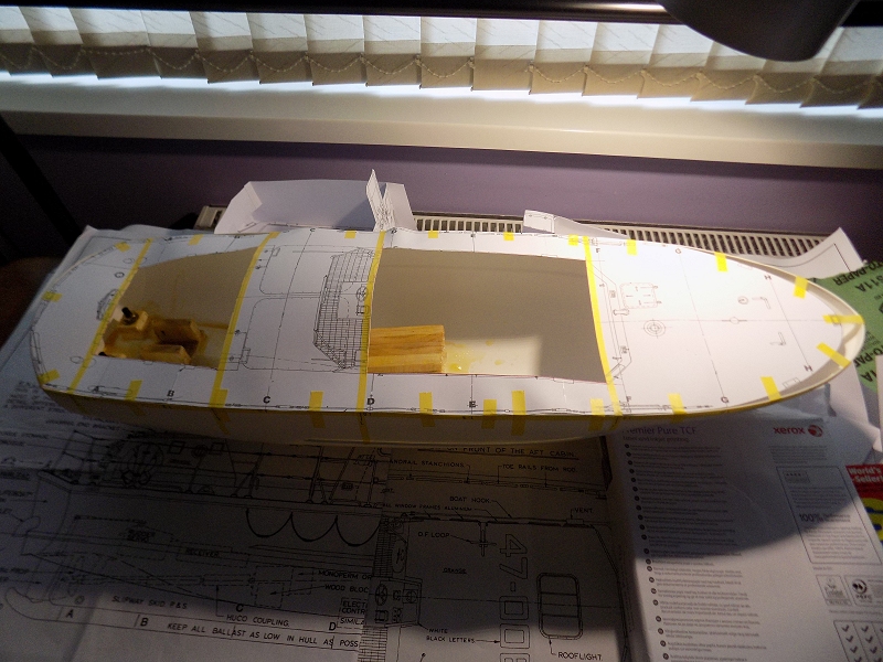
Made a litle progress ... nothing lines up as it should so everything takes longer ... first step to making the deck, print a template at correct size so i can mark off the sections A to H + the aperture edges. Note the big gap at the front - the hull is at least 20mm too long, plus (probably not visible in the photo) the stern end top is about 10mm too high in the middle.
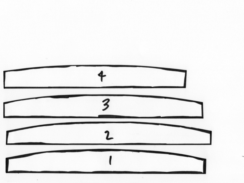
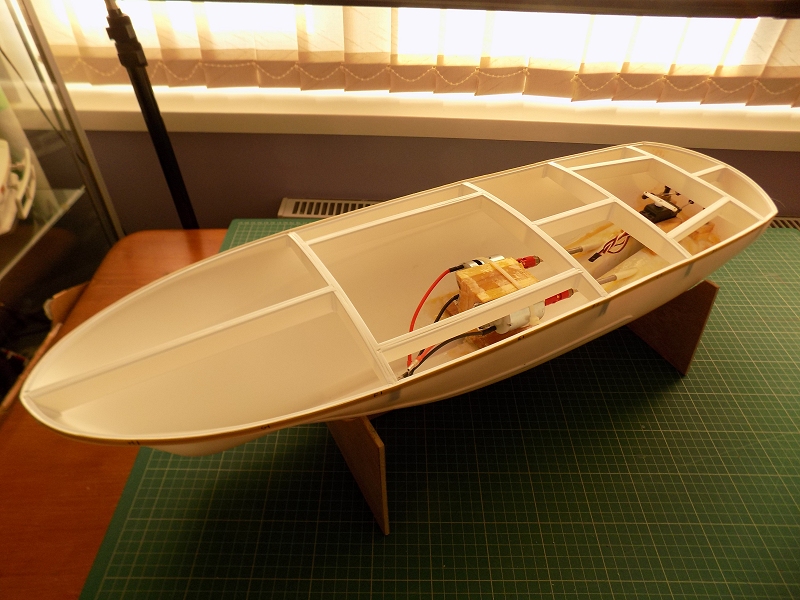
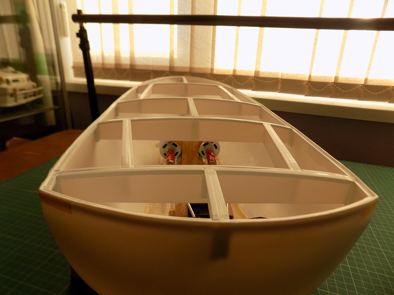
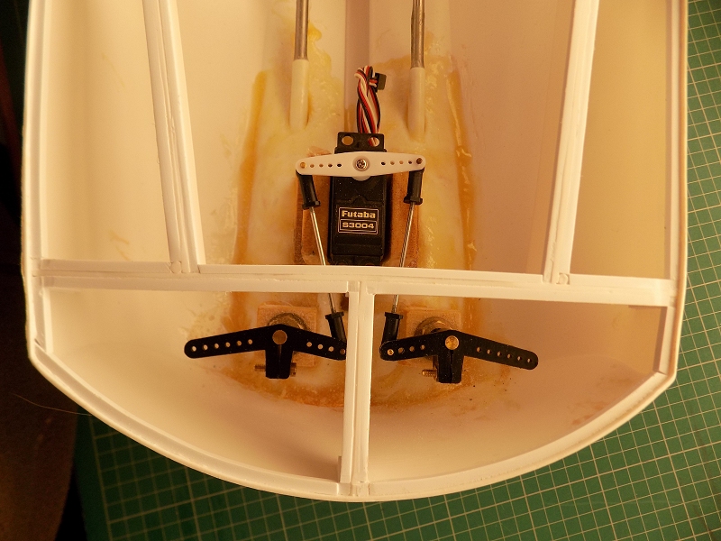
Final templates (3rd or 4th attempt) for the laternal deck beams: Starting on templates for the stand: Progress so far: stand mostly done, deck beams in (along with bracing & load spreading strips), rudders, props & motors also fitted as I wasn't convinced access was going to be adeqaute once the deck plates are glued on ... Note curved deck: Rudder setup ... not that attractive, but both rudders move the same way on a single servo, and it maximises rudder throw without putting any strain on the servo:
The following user(s) Liked this: Edou
|
|
Please Log in to join the conversation. |
1:18 RNLI Tyne Class Lifeboat Build 7 years 5 months ago #41627
|
Nice
|
|
Please Log in to join the conversation. |
1:18 RNLI Tyne Class Lifeboat Build 7 years 5 months ago #41628
|
I like the rudder servo setup! Nice
Signature now gets correct formatting if you edit it in your Profile. Use normal BBcode if you want.
www.tamiyabase.com was formatted automatically. |
|
|
Please Log in to join the conversation. |
1:18 RNLI Tyne Class Lifeboat Build 7 years 5 months ago #41629
|
Great story, Jonny!
The build should be great altough the build looks hard... -Lrs
Signature now gets correct formatting if you edit it in your Profile. Use normal BBcode if you want.
www.tamiyabase.com was formatted automatically. |
|
|
Please Log in to join the conversation. |
Time to create page: 0.183 seconds

