TOPIC:
Blakbird's 56020 Leopard 2A6 Build 3 years 7 months ago #61775
|
We'll go back in time a bit for this one. The Leopard 2A6 1/16th tank was only the second RC model I ever built. This is not exactly a beginner's kit and you could argue I had no idea what I was getting into. Still, it came out well..
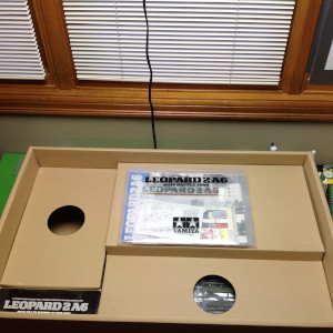
After my experience with the King Hauler, I was very eager to try another Tamiya project but I wanted it to be something different. Enter the Leopard 2A6 1/16th scale main battle tank. I took a gamble here because I had never built a tank and this is one of the most expensive single items offered by Tamiya. I was pretty worried I would screw it up. This is called a "full option kit" and I was interested to know whether this was accurate or if I would need to buy a lot of accoutrements to make it good enough. Let's find out! Tamiya's line of 1/16th scale RC tanks is legendary. In fact, the very first RC model Tamiya ever made was the RT-1601 M4 Sherman way back in 1974. Over the years new tank models have come out rarely but tend to be the pinnacle of Tamiya technology and ingenuity. Except for the very earliest models, the large scale tanks tend to include working turrets, recoil firing mechanisms, and realistic sound effects. The 56020 German Leopard 2A6 was released and 2004 and includes all of these features and more. There are even numerous fiber optically lit lighting modes. In addition to the technical details, the tank series is absolutely loaded with scale details. This is as much a scale plastic model as an RC model. Every conceivable detail right down to the backup camera and smoke canisters is included. The price makes these models prohibitive, but every Tamiya fan should have at least one in their collection. I don't usually like to spend a lot of time and effort describing the "unboxing", but this model is an exception as you will see. There is a lot to see in this box and Tamiya really put a lot of effort into showcasing the model, not just containing it for shipping. 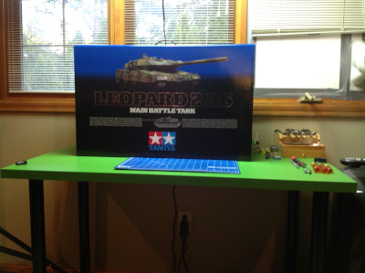
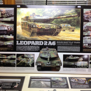
This is a really impressive and imposing box. Some may say that it not worthwhile to put a bunch of design time and money into packaging, but this certainly conveys a sense of quality and care. The box is large, smooth, sturdy, and printed in brilliant color. It has a carrying handle on the top and a flap which opens in front. Once the flap is open, some detail pictures of the full scale tank are displayed, a list of model features is shown, and several windows in the box show important parts contained within. 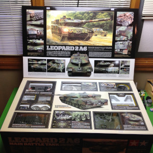
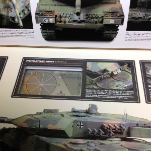
These pictures show a closer view of the left and right side of the window portion of the box. There are 10 total windows showcasing some really diverse parts and features including the tracks, the sprockets, the control unit, the speaker, and some photo etched parts. 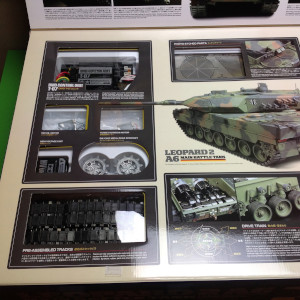
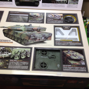
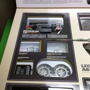
The lower left window shows the tracks. At this point I was not sure what they were made out of. You can also see the metal main drive sprockets and the "HV Unit". I had no idea what the HV unit was for, and in fact didn't figure this out until almost the end of the build. The upper left windows (right photo) show a couple of small motors used for turret rotation and main gun elevation as well as the DMD Control Unit. Similar to the MFC on the King Hauler, this unit controls lights, sound, and acts as a motor controller. 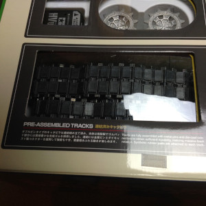
The following user(s) Liked this: stingray-63
|
|
|
Please Log in to join the conversation. |
Blakbird's 56020 Leopard 2A6 Build 3 years 7 months ago #61776
|
The middle upper section shows some photo etched metal parts which have some very fine detail. I suspect these are quite fragile. The lower center part is not a window but a diagram showing how the motors are used to control the model. It turns out this is really fascinating and will be discussed further as I build the transmission.
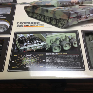
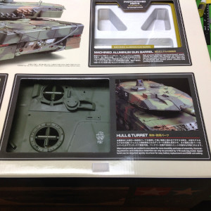
The upper right side shows the speaker. Below that are some curved photo etched parts and the machined aluminum barrel. It is important that the barrel be heavy and stiff or it will bounce around with a low frequency that clearly identify it as fake. Finally, the lower right shows the top of the turret. The plastic is molded in a nice dark green, but I'll still be painting pretty much everything. 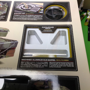
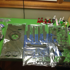
Once you take the lid off the box, you see this. The upper level of the box is divided into 3 sections, most of which were visible through the display windows in the cover. Once the upper level is removed, you can see the lower level which contains 4 section. The upper left section is empty. The section on the lower left contains the hardware and electrical parts and is really heavy even though it is the smallest area. The lower right section contains most of the plastic parts trees. The upper right has some of the big monolithic parts like the main hull.The assembly manual, operating manual, and decal sheet are protected between the layers. 
When I first saw this I was thinking that the model was going to be built from a few very large parts, but this proved not to be the case. There are hundreds of tiny plastic parts to be installed as well as hundreds of fasteners. Unlike the King Hauler, this has aspects of a traditional plastic model and therefore there is plenty of painting, gluing, and cementing to do once the mechanical portions are complete. 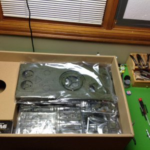
|
|
|
Please Log in to join the conversation. |
Blakbird's 56020 Leopard 2A6 Build 3 years 7 months ago #61777
|
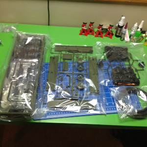
These photos give you an idea of how many parts there are. Almost everything is molded in green, but there are also a couple of black trees and one clear. Every tree comes bagged to protect it during shipping and to contain any parts that might come loose.
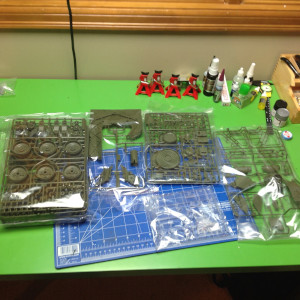
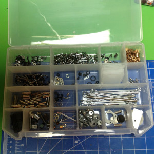
There are five hardware bags labelled A-E and another pile of unlabelled bags. Unlike some other Tamiya models, certain bags don't go with certain steps. You need to open them all because you may need any part at any time. I used a plastic bin to store the parts with one compartment for each bag. This made it easy to find what I was looking for without risking losing anything. You can see some tiny roller bearing balls near the upper right which had to be carefully contained. 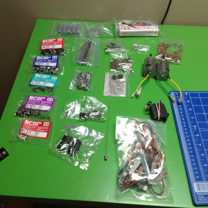
Finally, the instruction manual. The manual came in its own thick protective plastic folder along with a decal sheet, a painting guide, and a parts list. The parts list is a separate pullout section for reference so you can easily look up the shape and size of any part you might be looking for. Tamiya really worked hard to make this as logical and organized as possible. After the usual introductory section covering tools and supplies needed as well as safety warnings, the manual begins with a fairly extensive section on the history and properties of the real German Leopard tank. This is presented is 3 different languages (Japanese, English, and German) and includes a page of statistics. There is also a full page labelled diagram with 30 named parts of the real tank. The building instructions don't finally start until Page 12. 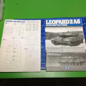
|
|
|
Please Log in to join the conversation. |
Blakbird's 56020 Leopard 2A6 Build 3 years 7 months ago #61778
|
I often find the transmission to be the most interesting part of a model build, and this is no exception. Even though this transmission does not have multiple gear ratios, it has other qualities which make it different from most traditional gearboxes.
Step 1 starts right off with the transmission. This step is entitled "center differential" but that's a bit of a misnomer. This can't properly be called a differential because it has no ring gear, therefore it has only 2 inputs/outputs rather than 3. It is really just a 1:1 reversing gearbox. What goes in one side comes out the other in the opposite direction of rotation. On the other hand, the housing is prevented from rotation so you could think of it as a locked ring gear. The parts inside are the same as a standard differential and include two bevel gears and 3 pinions on a carrier. The gears need to be lubricated with the included ceramic grease. The housing appears to be made from a fiber reinforced Nylon, the same material used for the plastic gears. 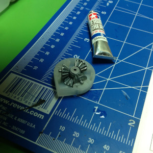
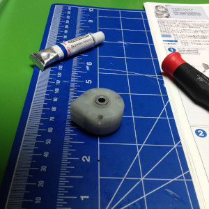
Step 2 builds a matched pair of outer differentials, this time the real thing. The parts inside are the same as the center diff, but the outer housing includes a spur ring gear. The bevel gears on either side have an integral internal spline which is used to pass torque into and out of the differential. Splined axles will plug into these. 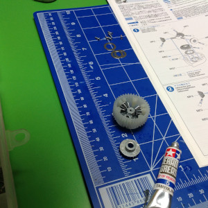
Now things start getting interesting. Step 3 combines all the differentials onto a common axis. Note that I said axis, not axle. There are two axles, one coming out either side of the central diff which spin opposite directions. The center diff is indexed so it cannot spin within the transmission housing. The additional spur gears you see between the differentials ride on ball bearings and therefore are not locked to the axle. They are effectively idler gears. In the background you can see a pile of ball bearings. This kit comes with a partial supply of ball bearings, including everything inside the transmission. In other places on the model, metal bushings are used. These will be discussed when we get to them. 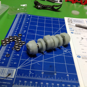
The second transmission shaft is even harder to explain, and it takes two steps (4-5) to build it. This is one continuous shaft rotating at one speed. From left to right (right hand image): 1st pinion gear is locked to axle, 2nd bevel gear is free, 3rd spur gear is free, 4th bevel gear is free, 5th spur gear is locked, and 6th pinion is locked. The pinions at either end control output to the track sprockets through the left and right differentials, so it is really that 5th spur gear that drives them. 
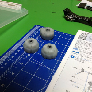
Step 6 builds a pair of bevel and spur gears which freely spin on axles. These will be the inputs from the motors. 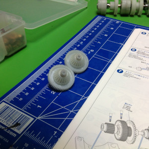
The following user(s) Liked this: stingray-63
|
|
|
Please Log in to join the conversation. |
Blakbird's 56020 Leopard 2A6 Build 3 years 7 months ago #61779
|
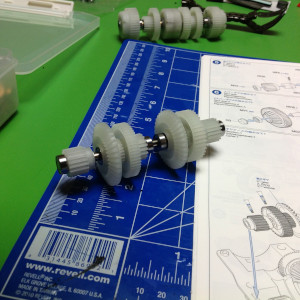
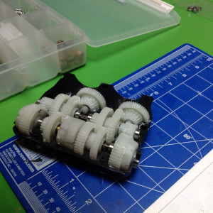
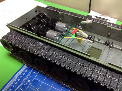
Step 7 finally shows how this whole thing goes together, and it is cool. In theory it is very easy to power a skid steer vehicle. You just connect one motor to each side and then control them independently. In practice, the problem is that this makes it almost impossible to drive straight because the motors are never operating at exactly the same speed. Enter the dual differential drive. In this setup, one motor is used for propulsion and drives both sprockets equally. The other motor is used for steering and drives the sprockets in opposite directions. These systems are summed with differentials such that combination of the two is possible in any proportion. This nicely solves the problem of going straight, but also means that you need twice as much power in your drive motor because you are only using one. That's why this tank uses 540 sized motors while many of the others use 380 motors.
The motors' inputs at the top of the image and drive the large spur gears. The bevel gears make the 90 degree corner and pass through two idler stages before coming back to the small pinions. It is convenient to use the same axles for the idles gears because it saves space. The left hand input is the drive motor. After the two idler stages, it drives the large spur gear on Axle 2 which is locked to the pinions. These pinions drive the ring gears of the outer diffs, thus turning both sprockets in the same direction. The right hand steering motor has almost the same path except that the spur gear is not locked to Axle 2, instead it uses another spur gear locked to the right side of Axle 1. This forces the left side to rotate the opposite direction. Note that steering also has more reduction than drive which is useful because steering takes a lot more power to skid the tracks. 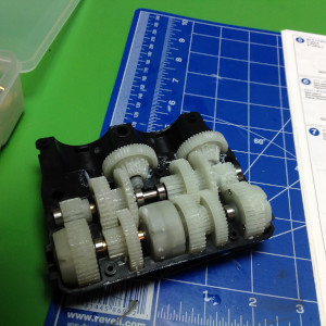
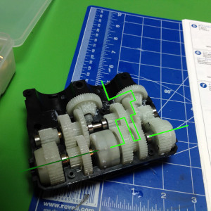
Update: Reading this back years later, I can see how difficult it is to understand the transmission without some further explanation and visualization. I'll try to do better. Let's use some torque diagrams to show what's happening. The key to understanding is knowing that some gears can rotate freely on their axles while others are locked to their axles' rotation. There is no way to know just by looking at a photo, you have to study the instructions. I'm going to go through the painful process of counting teeth off the instruction pictures to figure out the gear ratios here. The first picture shows the drive system torque path in red. Staring with the motor (which isn't installed yet), we have a pinion and spur with 18:52. The second stage bevel gear pair is 18:36. This gear is NOT locked to Axle 2. The third stage spur gear pair is 24:52. This gear is NOT locked to Axle 1. The fourth stage spur gear pair is 18:39. This gear IS locked to Axle 2 so this axle is now locked to the drive motor which powers the final pinions on both ends. The output to the differential (fifth stage) is 18:39. Note that because we are driving a differential spur gear but one side is locked (by connection to the steering motor), we get an additional 2:1 ratio on the output. If my math is right, the final drive ratio from the motor to the sprocket is 29.4:1. The second picture shows the steering system torque path in green. Staring with the motor (which isn't installed yet), we have a pinion and spur with 12:52. The second stage bevel gear pair is 18:36. This gear is NOT locked to Axle 2. The third stage spur gear pair is 24:52. This gear is NOT locked to Axle 1. The fourth stage spur gear pair is 24:52. This gear is NOT locked to Axle 2. The final stage spur gear pair is 18:39. This gear IS locked to Axle 1 so this axle is now locked to the steering motor which powers the output differentials through the center differential which forces them to rotate in opposite directions. If my math is right, the final steering ratio from the motor to the sprocket is 88.2:1. After everything, there is exactly a 3x difference between the drive ratio and the steering ratio, and all of that comes down to a different pinion (1.5:1) and the 2:1 in the output drive differential. 
Step 8 puts the cover on the transmission and hides all that lovely rotating goodness. Now it's just a magic box. 
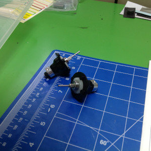
Step 9 prepares the two motors by applying a gasket, an anti- rotation block, and a pinion to each motor. The motors are the same, but the pinions have a different number of teeth. The steering motor is geared lower. 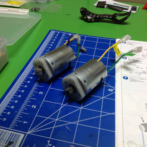
Step 10 attaches the motors to the gearbox housing, completing the transmission. At this point nothing is stopping us from hooking up the control system and trying it out, which of course is exactly what I did. I connected the motors to the control unit, and the control unit to a receiver and a battery. It is very easy to see the mixing of steering and drive happening by watching the output axles. I also removed the housing top cover so I could see the gears in action and better understand the function of the transmission. Given the huge face width on all of the gears, it is quite likely I will never need to open this for maintenance again. That's a good thing because it turns out that accessing the lower hull once the model is completed will be very difficult. 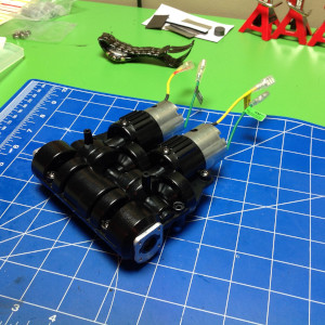
|
|
|
Please Log in to join the conversation. |
Blakbird's 56020 Leopard 2A6 Build 3 years 7 months ago #61783
|
Step 11 begins construction of the driving mechanism of the hull. We start with the drive shafts. These come directly out of the gearbox and feed the sprockets. The thin shafts you see don't carry torque, they just center the shaft in the differential. Torque is carried between the spline and the hub.
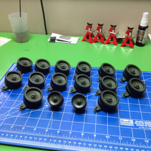
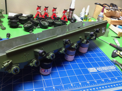
Next come the 14 road wheels in Step 12. You see 16 in the picture but the bottom two are different. These are the tensioning sprockets which go at the front of the track. I first sprayed all the parts in NATO Green, then assembled them. After the paint was dry, I attached the rubber tires over the road wheels as you can see in the second image. 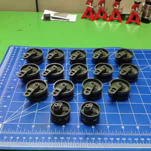
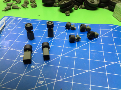
Next up come the 10 shock absorbers in Step 13. There are actually 4 types. Left and right are mirrors of each other and the two at the left end have a slightly different pattern on the can. Although there are springs inside, these serve only as scale details and don't add anything to the suspension of the model. They soften the impact of the swing arms against the stops in the event the torsion rods bottom out. 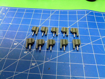
Step 14 installs the bearings and axles for the torsion bar suspension. The kit comes with metal bushings here. I had already ordered ball bearings to replace all the bushings in the set, but it turns out I could have saved myself some money here. These are not high speed rotating shafts, these are just suspension joints. One could argue the bushings are actually better because they will resist ingress of dirt and water better. However, I already had the bearings so I went ahead and installed them (24 bearings). 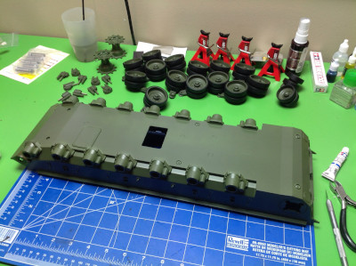
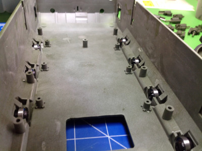
Step 15 is the return rollers. These serve only to hold the track up on its journey from the tensioning sprocket back to the drive sprocket. I first painted and assembled them and then painted the tires flat black. Unlike the road wheels, there are no rubber tires provided here so paint will have to provide the illusion. 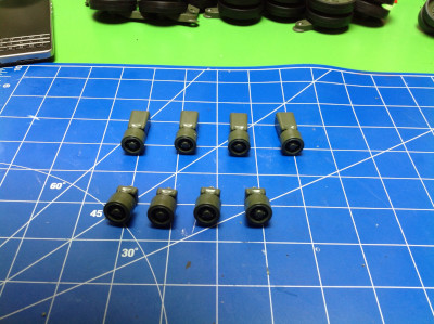
|
|
|
Please Log in to join the conversation. |
Blakbird's 56020 Leopard 2A6 Build 3 years 7 months ago #61784
|
Now the torsion bars and return rollers are installed. The torsion bars travel the width of the hull and are attached to the road wheel axles at one end and anchored to the hull at the other. These twist up to about 30 degrees under wheel loading and seem to be very durable. The spring rate seems to be also about right for the weight of the vehicle. As a consequence of the offset torsion bars, the wheels on the right and left of the hull are not aligned but are offset about 1 cm. MUCH later I discovered that I had used the wrong screws in this step when I did not have the correct number left for another step in the turret. I had to tear the whole model apart down the this hull base to extract them.
The return rollers are glued to the hull and cantilever quite a long distance. For this reason they are pretty fragile so you need to be careful not to put too much weight on them. 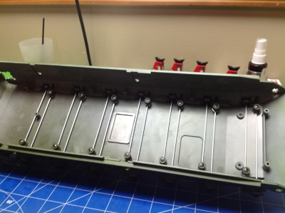
Step 17 glues on the shock absorbers. This is a very simple step. There is an index mark to show where each goes on the hull. 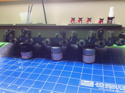
Step 28 attaches the road wheels. Every one of these 14 assemblies is the same so you can't screw it up. You only need to make sure that each swing arm is angled back. Now you can set the tank on its wheels and try out the suspension. At this point the model is still very light so the suspension doesn't feel right. 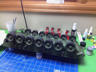
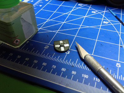
Step 19 tells you how to cut out photo etched parts. This is fairly important because this is very thin sheet metal and some of the parts are tiny and all are fragile. You don't want to twist them to remove them from the tree or they will get warped. The photo shows how small the smallest is. 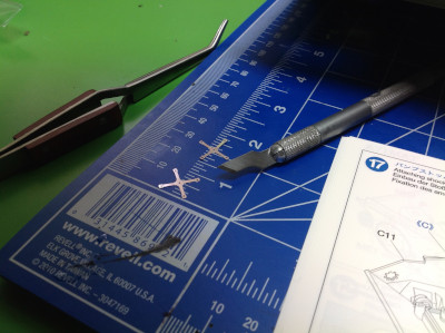
Step 20 builds some accessories for the rear of the hull including a pintle hook, a couple of shackles, and a convoy marker. The convoy marker is shown in the right hand image. The tiny metal photo etched part needed to be bent into the small tower in the middle, and beneath is a clear cone for light. The white stripes are decals: the first in the model. The whole thing is only 1 cm wide. I didn't expect to be dealing with such small parts in such a big model. 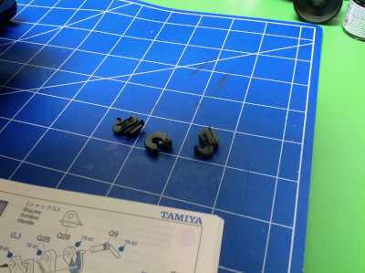
Step 21 installs a bunch of bits to the rear of the hull including the assemblies from Step 20 and some exhaust ports, tail light lenses, and panels. At this point I still need to paint those lenses transparent red. I didn't have any such paint yet and the hobby store was closed so I just kept building. Of course, the very next step blocks access to these so disassembly was required the next day to paint them. Once I am on a roll building, I can't stop. 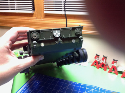
|
|
|
Please Log in to join the conversation. |
Blakbird's 56020 Leopard 2A6 Build 3 years 7 months ago #61785
|
Step 22 installs the transmission and output axles into the hull. The assembly order means that if you ever want to remove the transmission for maintenance (or access) later, you first need to remove the tracks and the axles which insert from the outside.

The main drive sprockets are the first cast metal parts. These needed to be primed and painted prior to assembly. 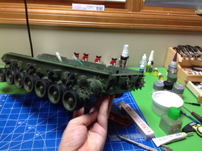
And now the tracks! The tracks come pre-assembled as a single piece and are tensioned by rotating the forward sprocket. Of course I threw in a battery and drove the hull around at this point. I was surprised by how fast it is. In the right hand image you can see the results of a dry brushing technique I used to weather the tracks and make them looked like scratched metal. Although it looks good, this was folly for two reasons. First, all the paint wore off the first time I drove the tank. This kind of detailing only works on static models. Second, the real Leopard tank has rubber pads on the track just like the model, so these would never look like worn metal anyway. Some rust on the areas underneath would not be amiss though. 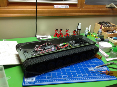
Step 25 is the speaker box. The speaker is screwed down into the box and various wires for the hull are routed through it. The box makes an effective acoustic chamber and really amplifies the apparent volume of the speaker. The fact that wires will be passing from the hull to the turret means that the turret will not be able to rotate 360 degrees without fouling the wires. 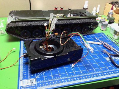
To complete the hull, the speaker box is installed in Step 26. Oddly, it is not actually fastened down. It just sits on a couple of studs. 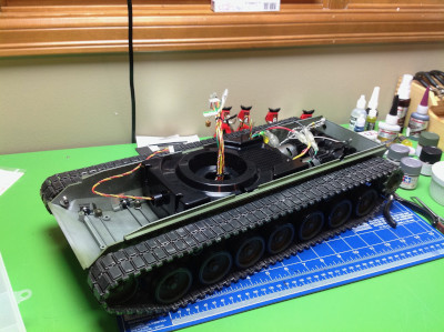
The following user(s) Liked this: 1972 LeMansGT Jim
|
|
|
Please Log in to join the conversation. |
") Are the metal tracks on there?
Are the metal tracks on there? ")
Blakbird's 56020 Leopard 2A6 Build 3 years 7 months ago #61789
No, the tracks are plastic with rubber pads. Metal tracks are available, but I think they would make it worse. Correction: metal tracks were once available, but they seem to be long since discontinued. |
|
|
Please Log in to join the conversation.
Last edit: by blakbird.
|
Time to create page: 0.396 seconds