Keyword

TOPIC:

CC-01s: RV, Unimog, Bedford TM, Valp, Ford CMP, Series 3 Land Rover, SD Revopak 9 years 10 months ago #29287

That lack of equilibrium sounds like bits flying around. :silly:
We'll assume the connected point is always rigid (which it really isn't vertically, but that would overcomplicate)...
I do believe both diagrams are correct, the diagonal force (weight) from the first one being equal to the shock's (diagonal) response as it is in the second image. It's just pushing back differently (redirecting horizontally) than it is being pushed upon.

:blink:

Please Log in to join the conversation.

Last edit: by Edou.

CC-01s: RV, Unimog, Bedford TM, Valp, Ford CMP, Series 3 Land Rover, SD Revopak 9 years 10 months ago #29300

Dash tidied up & shaped ... still waiting on the driver as that dictates everything else: driver -> drivers seat -> passenger seat -> what of servo cover etc is visible -> what they're disguised as; also driver -> steering wheel position -> instrument position -> rest of dash details...


First batch of bits painte: red primer & Vauxhall Brazil Brown on cabinets; grey primer & "chrome" on hub caps, sink unit top + cooker hood, white primer, VW Alpine White & clear on roof panels & door (latter not shown)...


... ditto for white on wheels, Tamiya Rubber Black & Semi Gloss Clear on edges ...


Ladder is 3/32" brass with soldered joints; added more details on body including reflector housings, reflectors same method as light lenses earlier;


Ladder worked so well I thought I'd do the rails the same. For some reason I could only find this size brass in 12" lengths so needed a join - I used tube, dremelled a slot in it & crimped in down to grip ... have run out of brass ATM :(


Starting on door mirrors:


Shiny new motor mount:

The following user(s) Liked this: stingray-63

Please Log in to join the conversation.

CC-01s: RV, Unimog, Bedford TM, Valp, Ford CMP, Series 3 Land Rover, SD Revopak 9 years 10 months ago #29307

Made some adjustments to the images for clarity. Resultant (the total original force) is now drawn in blue...
I think what can be concluded from the first image, is that under an angle some of the weight gets 'unsprung' and is translated into torque upon the damper (force drawn in pink) :


An alternative (but equal) way of composing this image :

Attachments:

Please Log in to join the conversation.

Last edit: by Edou.

CC-01s: RV, Unimog, Bedford TM, Valp, Ford CMP, Series 3 Land Rover, SD Revopak 9 years 10 months ago #29321

:silly: :silly: Crazy JR

Please Log in to join the conversation.

CC-01s: RV, Unimog, Bedford TM, Valp, Ford CMP, Series 3 Land Rover, SD Revopak 9 years 10 months ago #29325

This is just awesome Jonny, I can't wait to see it finished.
Do you think this is the start of a run of proper scalers?

Please Log in to join the conversation.

CC-01s: RV, Unimog, Bedford TM, Valp, Ford CMP, Series 3 Land Rover, SD Revopak 9 years 10 months ago #29329

Making my head hurt....
Don't remember much about vectors, but it looks like they're talking about movement caused by force rather than forces in equilibrium? eg if you were to apply force in a combination of blue & black directions, the shock wants to get pinged out in the opposite direction to the pink arrow, therefore, if the shock isn't getting pinged anywhere then the force required for equilibrium would be the pink arrow...
In the actual setup though, what force is pushing in the direction of the pink arrow?
In force diagrams, all angular forces are made up of horizontal and vertical components, so we're saying there's another set of horizontal & vertical forces present which are causing the pink arrow in addition to the black one?

Please Log in to join the conversation.

CC-01s: RV, Unimog, Bedford TM, Valp, Ford CMP, Series 3 Land Rover, SD Revopak 9 years 10 months ago #29330

Know what you mean. One of those things that can make your brain bubble. But there is definitely logic to it.

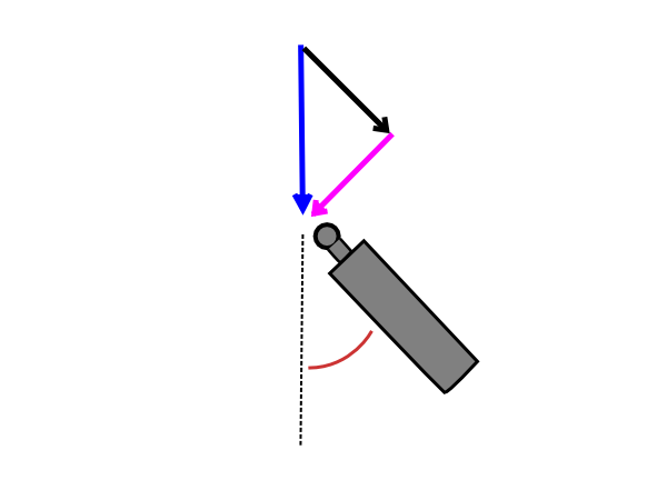
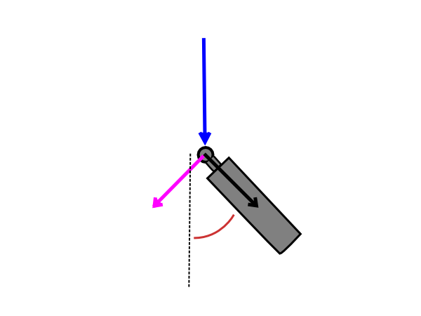
In my previous post, both images are basically the same.
The first one is just composed so it's easier to calculate each length/force.
Second one shows how you would think they actually work on the rigid connection (not floating a bit above of course, lol).

Blue is the actual force (in the previous post it is the weight of the car pressing down) and the other two are it's horizontal and vertical components. You could say blue is black and pink together.
One direction (black) is inevitably that of the damper but with that not the whole force (blue) is accounted for.
There has to be a perpendicular force (pink) that is the complement of black, together making them equal to the original force.
So part of the original weight/force gets unsprung (pink) and start acting as torque on the shock.
Not much the shock can do but resist that lever (other than breaking)...

In this image you can really forget the black arrows, the damper will just push (back) in the blue direction :


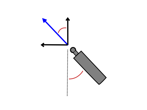
The black arrows are just interesting if you want to know how much is damped either horizontally or vertically.
But it will really do it's dampening parallel to itself (like the blue arrow/force).

Dunno it that was much clearer...
Attachments:

Please Log in to join the conversation.

Last edit: by Edou.

CC-01s: RV, Unimog, Bedford TM, Valp, Ford CMP, Series 3 Land Rover, SD Revopak 9 years 10 months ago #29331

I think the images were correct from the start, just not my reasoning.
One would really have to start with the acting force (weight in this case) and then consider the equilibrium (action = reaction).
Been a while and always preferred straight math over applied (to physics)...

Please Log in to join the conversation.

CC-01s: RV, Unimog, Bedford TM, Valp, Ford CMP, Series 3 Land Rover, SD Revopak 9 years 10 months ago #29332

Looked in my magic book of physics about vectors - pink arrow is defo wonky...
Vertical downwards moving force gets translated into movement in two directions - down at 45 degrees along the length of the shock, & slightly to the right as the wishbone pivots & the shock gets shorter. You can consider the horizontal component as resistance by the shock tower, friction from the tyre on the ground, or cancelled out by movement of the shock on the other side in the opposite direction, but it's there.
We're actually talking about the resistance to a turning moment rather than linear force, but in any case the pink arrow is the the result of re-adding an original component to the pre-solved resultant

Please Log in to join the conversation.

CC-01s: RV, Unimog, Bedford TM, Valp, Ford CMP, Series 3 Land Rover, SD Revopak 9 years 10 months ago #29333

There would definitely be more forces at play when you drive the car.
We can't really consider those though since JR's case was originally about how the shock angle influencing weight distribution.
So it's a rather static situation, only considering the force of the weight on the upper mount. That has no horizontal effect.
Only if you isolate the shock's parallel response to the weight, will it have a horizontal component.
And indeed if this force comes from the other side of the shock (actual road dampening).

Could it be the pink 'torsion' force looks off because 45 degrees is a ridiculuous angle (where it is at it's maximum)?
It will be rather small if calculated with a more commonly used setup...

Please Log in to join the conversation.

Last edit: by Edou.
Moderators: caprinutstingray-63AndyAus
Time to create page: 0.244 seconds
Cookies are required to make this site work. If you continue to use this site you permit us to use cookies.