

 The original 58072 Tamiya Avante buggy was released in March of 1988 to much fanfare because it was so complex and deluxe compared with anything else available at the time. Sadly, the performance does not appear to have lived up to expectations because it was superseded only a year later with the Egress, using a simplified chassis with better handling and durability. On the other hand, nothing compares to the sheer curb appeal of the Avante. Several people I've shown it to have used the phrase "work of art", and I've thought the same thing myself. It is a real beauty through and through and many unusual features are employed.
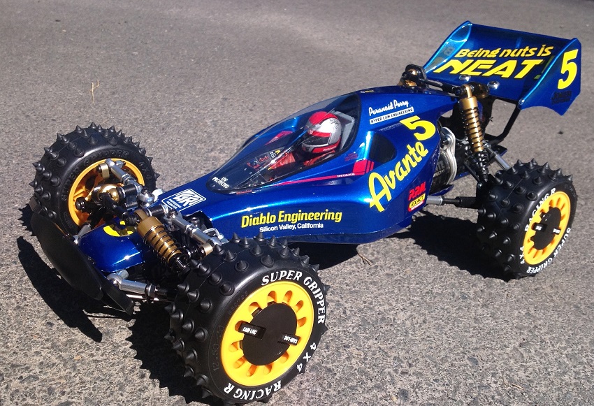
This is a 1/10th scale, 4WD electric buggy with carbon chassis (the original was FRP), many aluminum parts including all rod ends, and steel links. It has aluminum oil filled dampers, unique cam-loc wheel attachments, and a lovely scale body with driver and under tray. The spiked tires are a bit dated, but that's part of the charm. Of course you could easily use more modern wheels and tires, and the kit even comes with a set of standard wheels to use if you prefer. I find the performance to be quite good for a brushed Tamiya kit. It is certainly quicker than the standard 540 Mabuchi motor products. I've driven a lot of buggies but I don't race them, so my opinion is probably mostly useless, but I find driving it a lot of fun. On the other hand it is not cheap and it is not easy to find. There are cheaper and better performing buggies out there, but if you want pure class then you want the Avante.
Because the Avante was around for such a short time and was so expensive, it has always been pretty rare. At least that's true in the original incarnation. The name "Avante" has appeared on a host of other (marginally) related cars over the years.
 The 58085 "Avante 2001" was not released in 2001. It actually came out in 1990 (only 2 years after the original) so presumably the 2001 title was just to imply that it was futuristic. This was a reasonably close approximation of the original but with different front suspension and steering geometry and no metal rod ends. The retail price was about 30% less than the original Avante.
- The 58387 Avante Mk II was based on the DF-03 chassis and came out in 2007. With a totally different chassis, it is really only a successor to the original in appearance. This was only half the cost of the original.
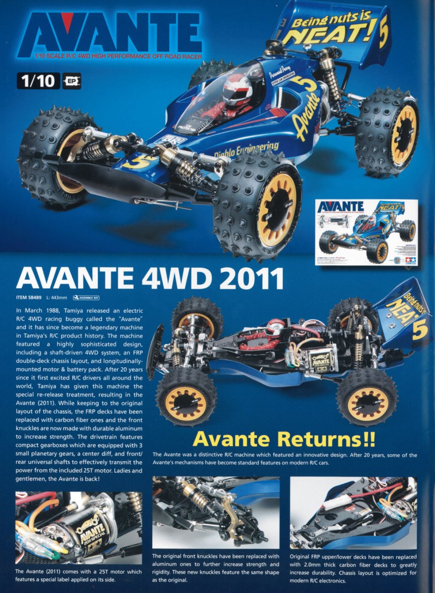
- The 58489 Avante is the one I have and is a 2011 re-release of the original with a few updates, most notably the electronic speed control. This later came in a 84270 pre-painted Black Special edition with different stickers. The production run of the 2011 edition was repeated in 2017 which allowed me to get one, and an additional batch became available in 2020.
- The 58550 Aero Avante was released in 2012, is based on the DF-02 chassis and has virtually nothing in common with the original except the general appearance and decoration. It is actually intended as an upscale of the 18701 JR Aero Avante Mini 4WD.
- The 58678 Comical Avante was released in 2020 on the GF-01CB chassis. This is a "chibi" version of an Avante on a short wheelbase wheelie chassis. It's not really even a buggy, but it does share the basic appearance of the Avante and actually looks pretty good, especially compared with some of the other pretenders.
- The 58696 Super Avante was released in 2021 on the brand new TD-04 chassis. It is really an Avante in name only since it has nothing in common with the original, or even with any of the later generations. It is a fairly high end chassis with inboard front shocks, but not like a TRF or an original carbon Avante.
Building the Frame
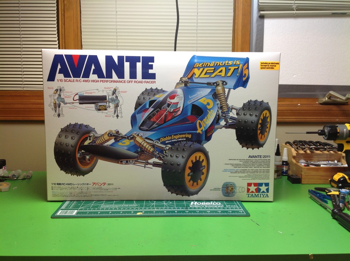
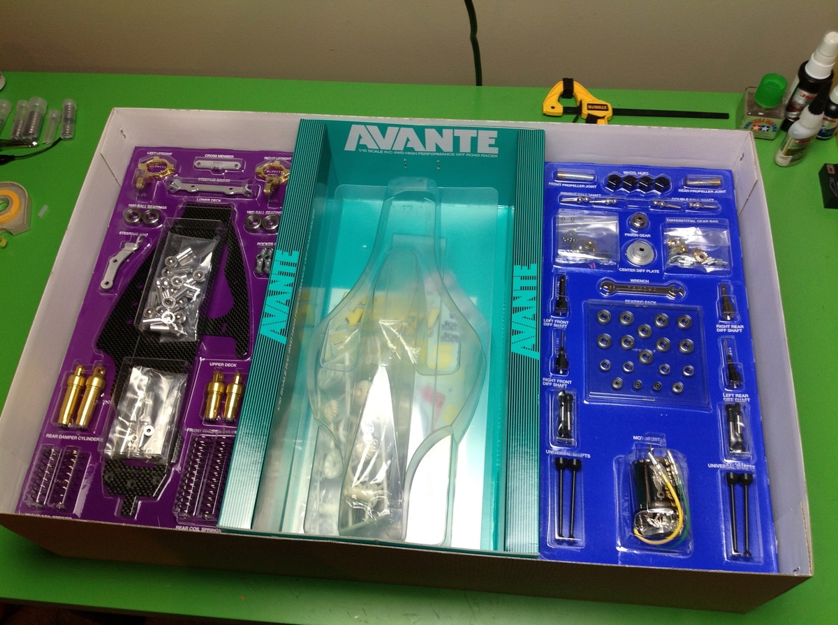
The Avante comes in a large, beautifully illustrated box. Inside the contents are divided into three sections. On the left and right are blister packs with some of the notable parts including the carbon chassis plate, the gold anodized shock bodies, ball bearings, special motor, and other metal parts. The center section has the polycarbonate body and under tray. Beneath these are the plastic part trees and hardware bags.
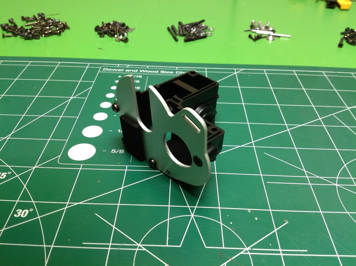
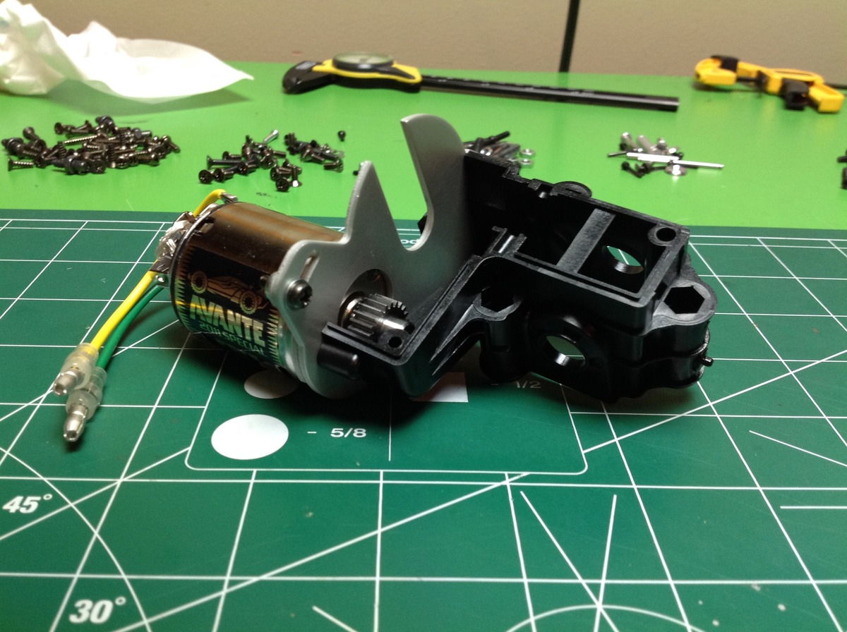
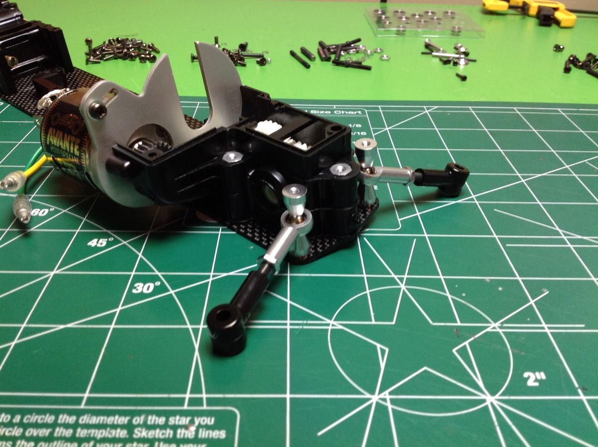
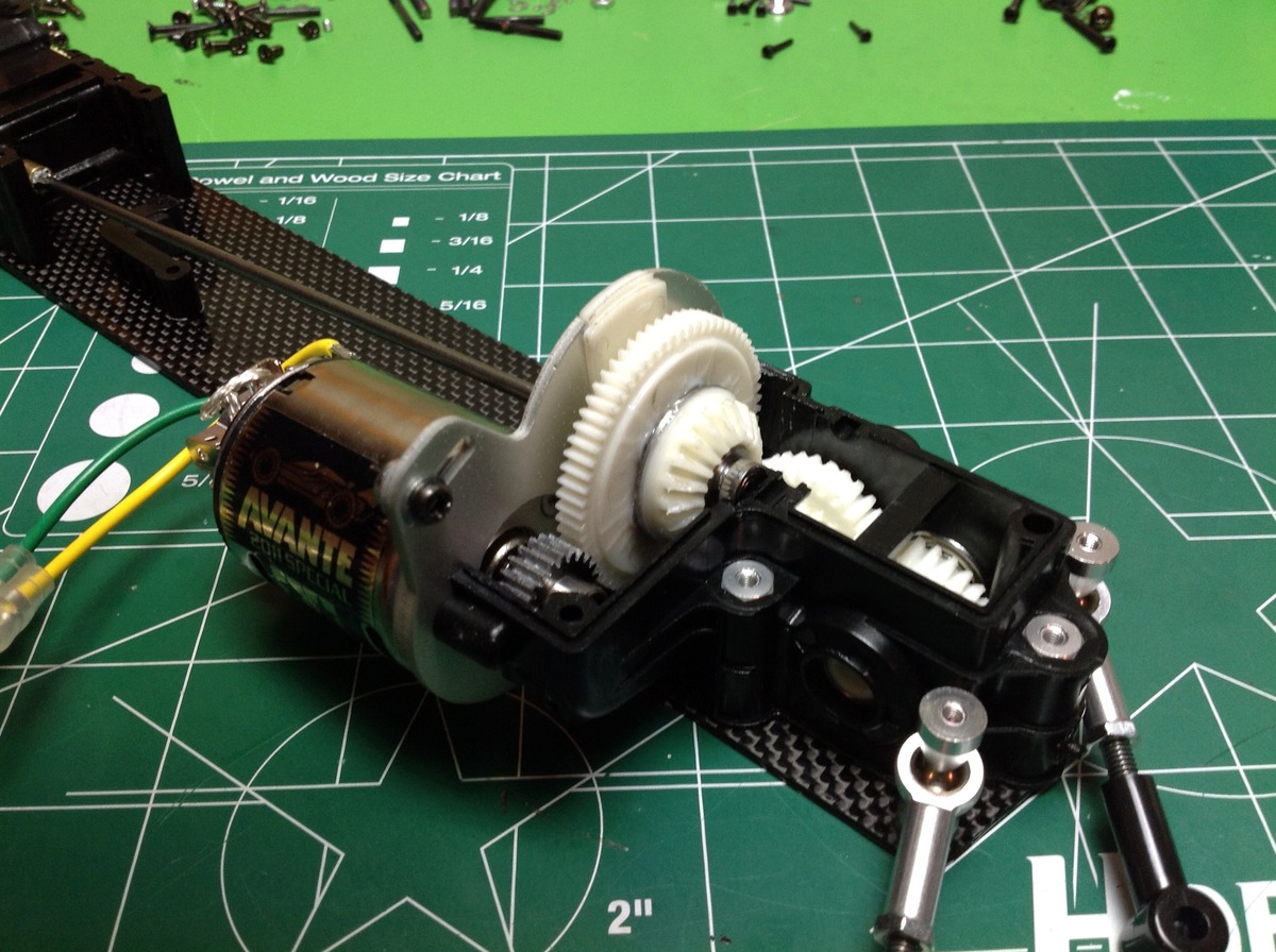
The assembly begins with the motor mount and rear gearbox. This is not just your standard Mabuchi 540 motor, this is a custom labelled, 25 turn, rebuildable brushed motor. It looks really nice. We'll see if it has an increased performance proportional to its looks. The model uses a 22 tooth aluminum pinion gear which I immediately replaced with a Robinson Racing steel gear of the same size. This is the only upgrade I made to the model.
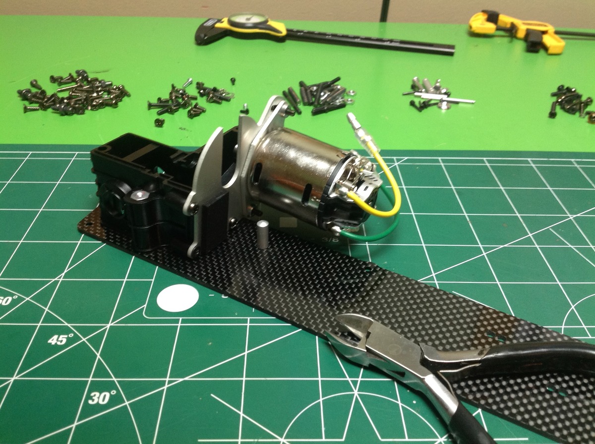
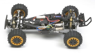
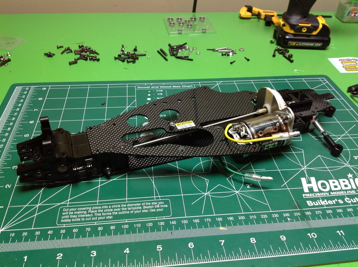
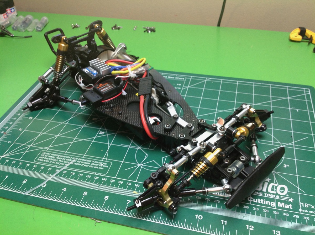
Here's the beautiful carbon chassis plate with the motor and aft gearbox housing attached to it. The use of a carbon chassis is the biggest and most obvious change from the original model which used an FRP (fiberglass) chassis.
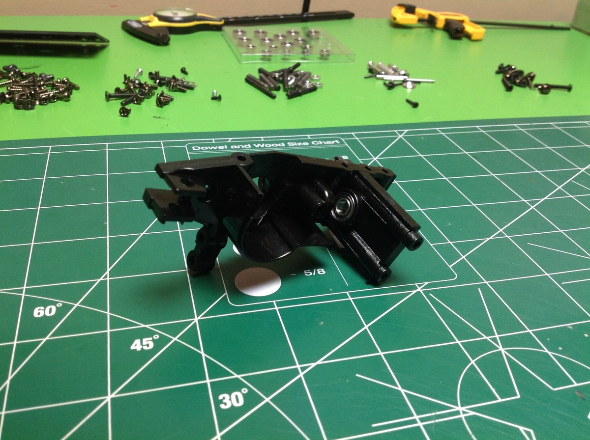
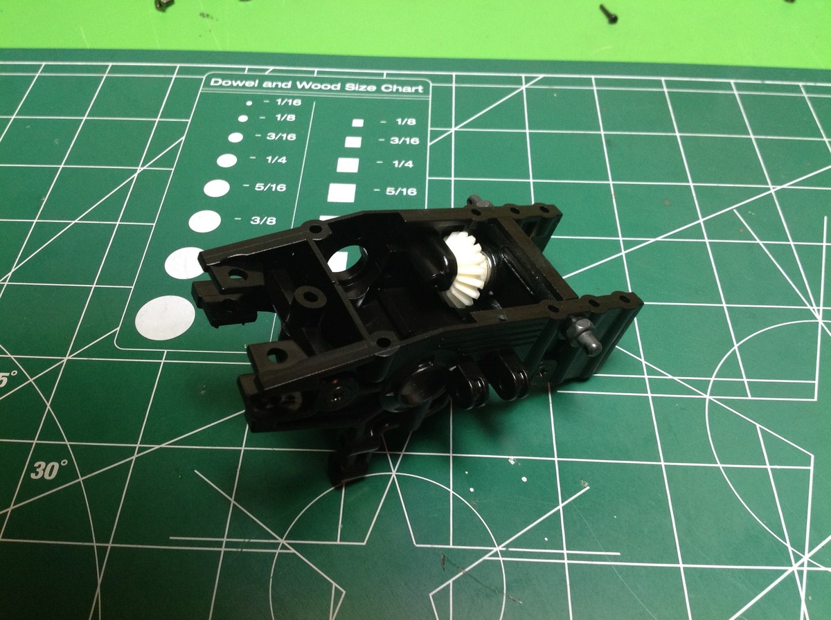
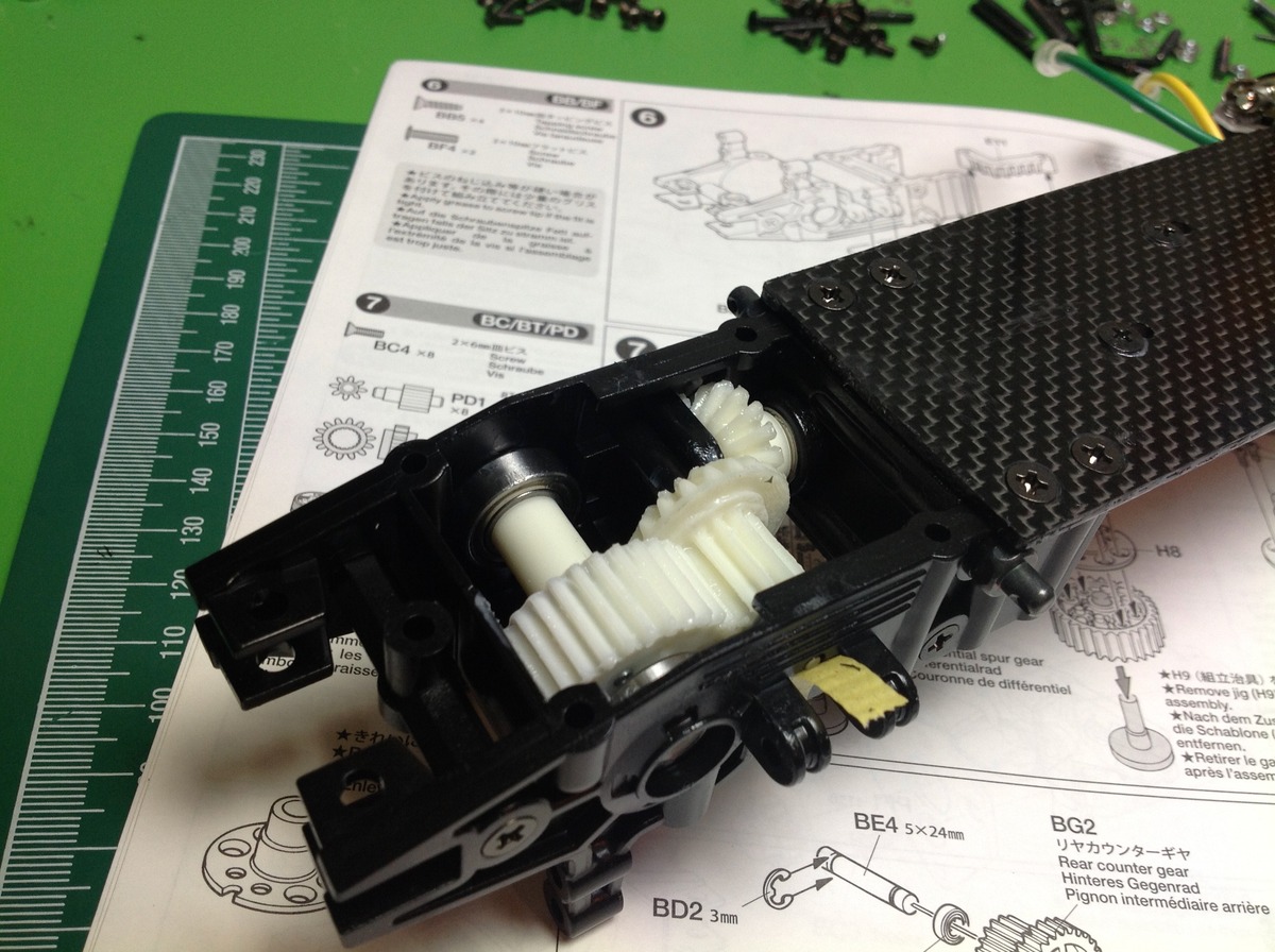
The front gearbox housing comes next. At this point, only a single bevel gear has been installed which rides on a floating axle. The end of this axle protrudes and will connect to the center drive shaft.
The front gearbox is cantileverd off the front of the chassis plate. At this stage in the build, the thin center is obviously the weak point between the thick ends.
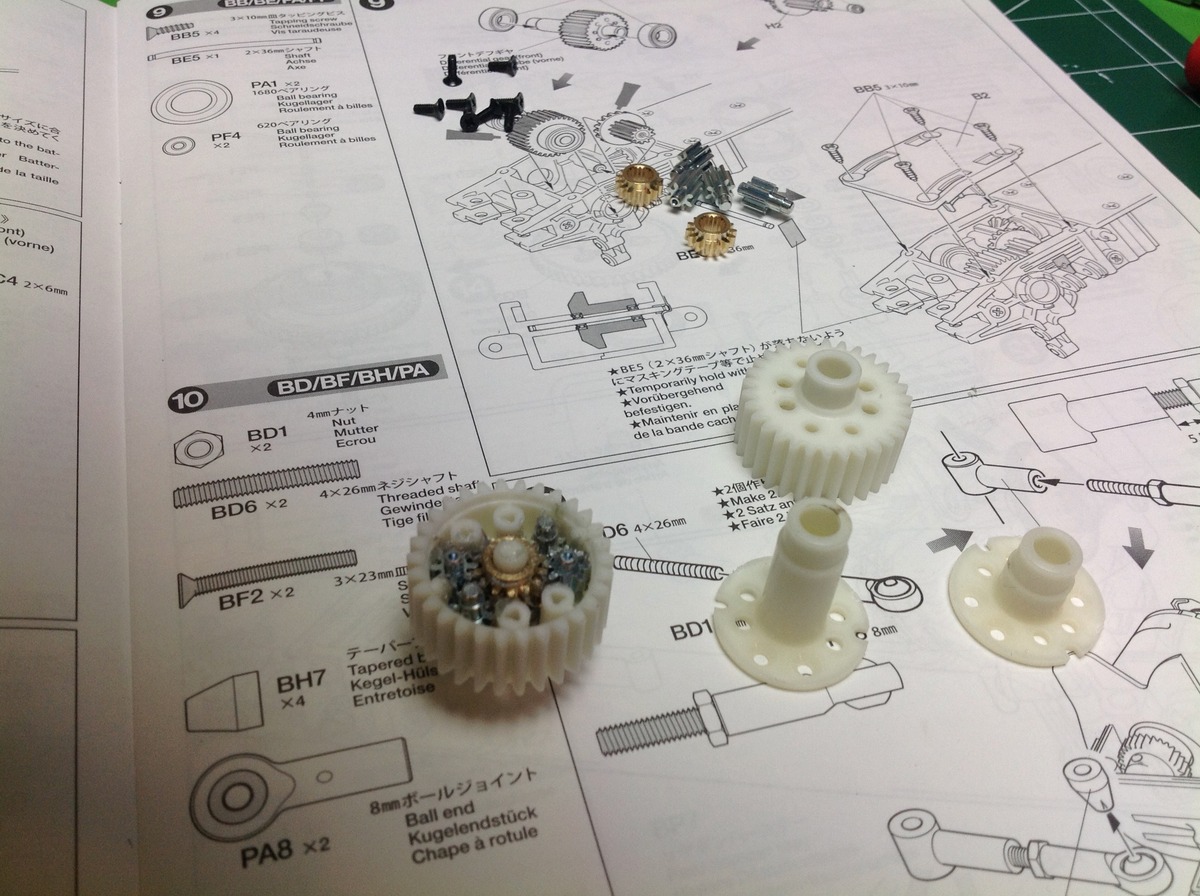
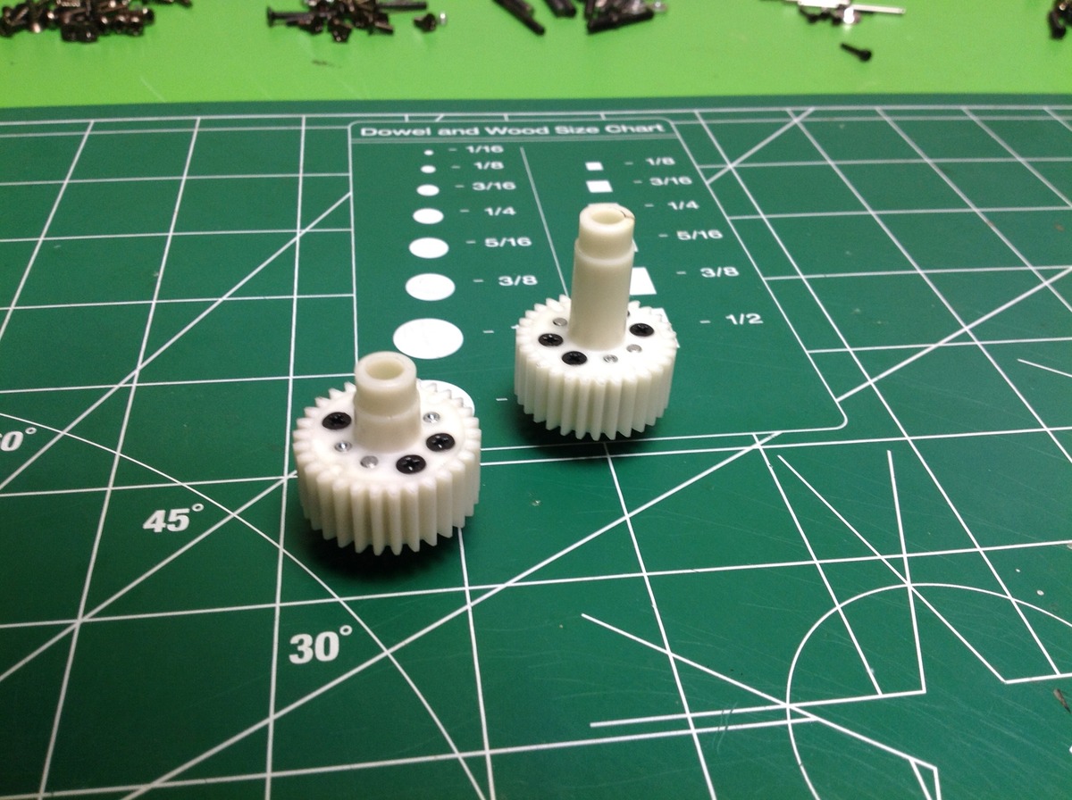
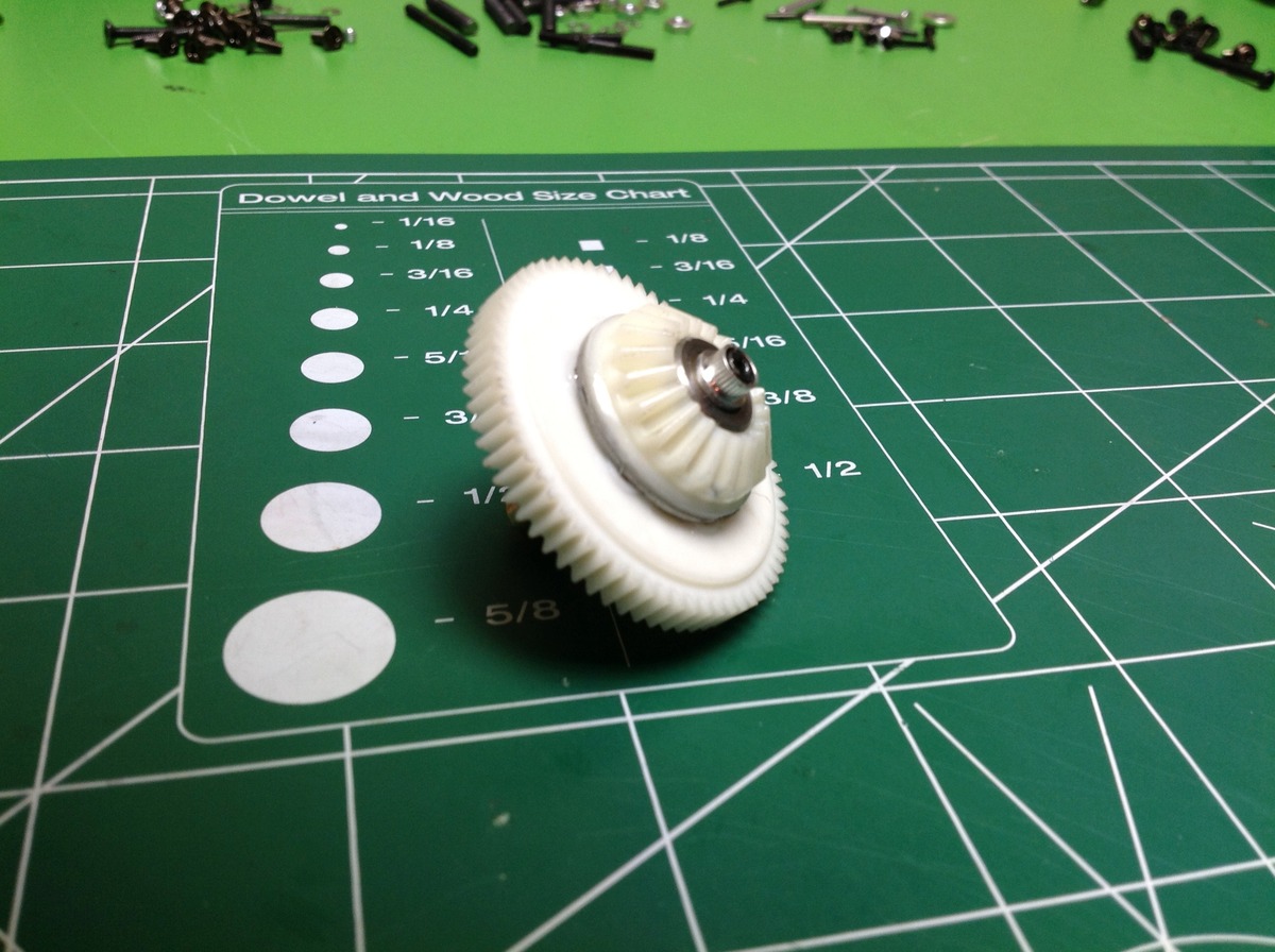
The front and rear differentials are internally identical but the front has a longer housing. The model uses gear differentials, but not your standard bevel gear type. These are planetary differentials using only spur gears. The first layer is an output sun mating with 2 planets. The planet axles are locked to the housing making it the planet carrier. The second layer is another set of planets and the opposite side sun gear. The two layers connect together with the planet gear teeth which rotate in opposite directions. The sun gears are splined to the axles. Note that the diff ring gear is not a bevel, which means the 90 degree turn will have to happen in another gear stage.
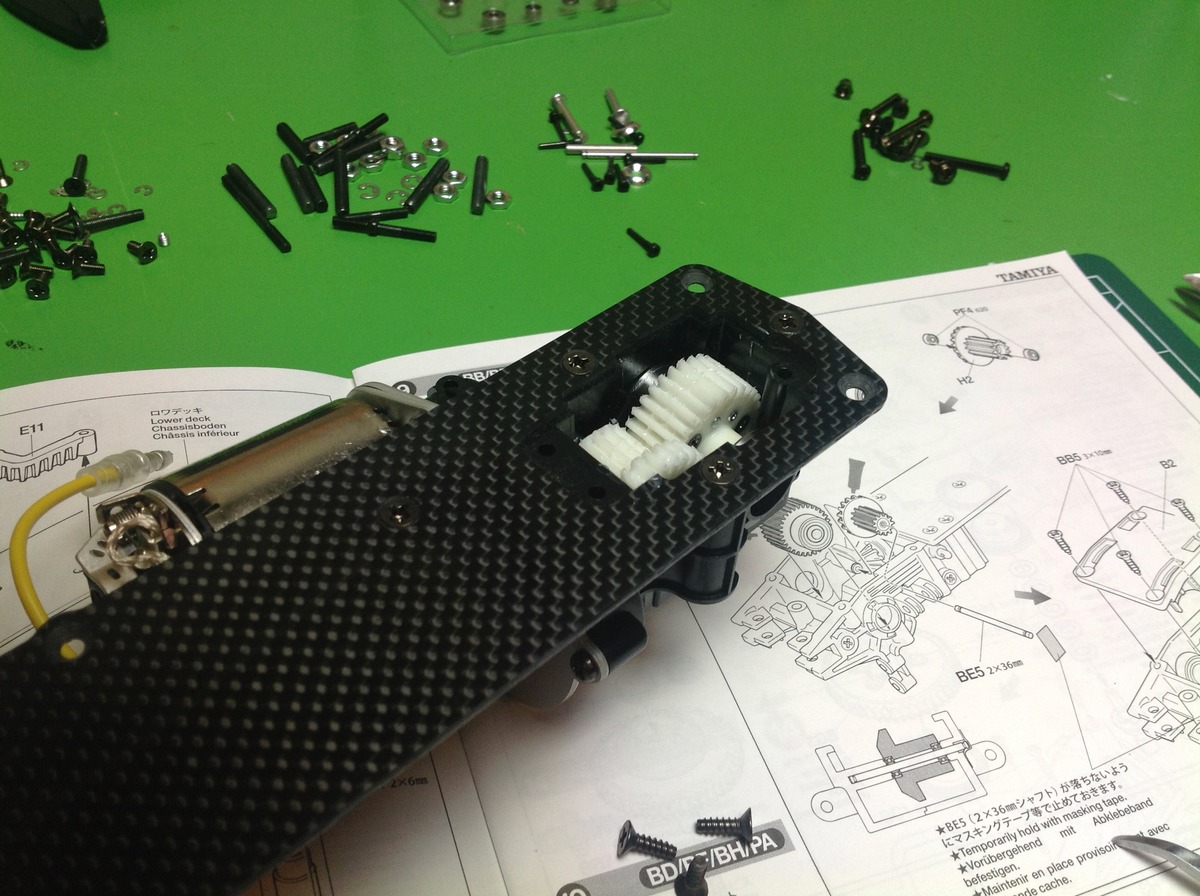
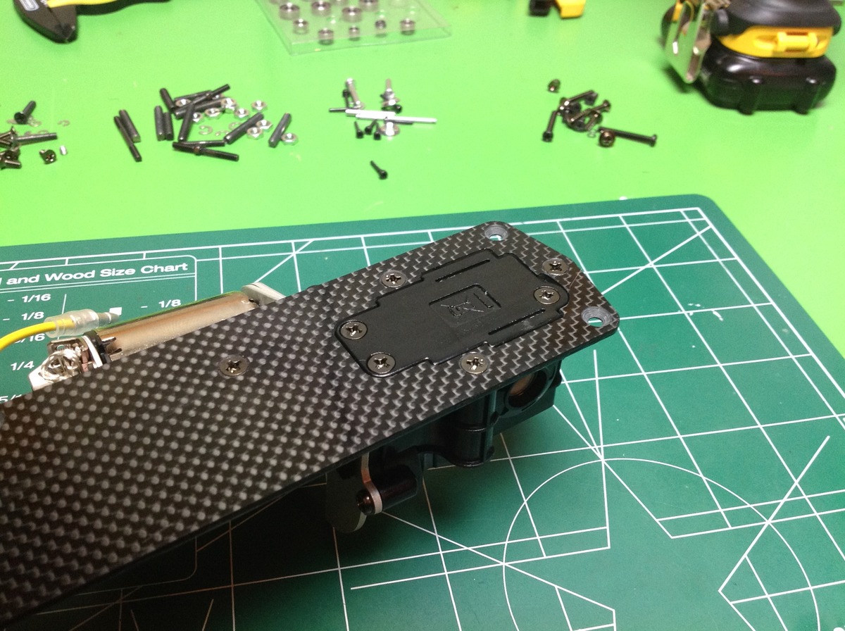
The rear differential drops into place from the bottom of the chassis and is then enclosed with a cover plate. This makes access easy for greasing, but you still need to pull the axles to actually remove it. Note the super wide face width on the spur gears.
Now we do the same thing for the front differential. The installation is similar to the rear except that the second stage is a bevel set instead of a spur set. The axle supporting the idler gear is inserted from the side and needs to be restrained with some tape until a part holds it in later.
Step 10 begins the installation of the suspension arms much earlier than the rest of the suspension. These are the rear lower arms which need to be installed now because they will be locked by the mid-plane chassis plate. In this case, the inside ball ends are aluminum and the outside are plastic. The outer ends are not balls but just sleeves. The thread between them is not a turnbuckle so the length can only be adjusted by removing one end and this means you need to get the lengths right now. A jam nut against the aluminum end locks everything in place.
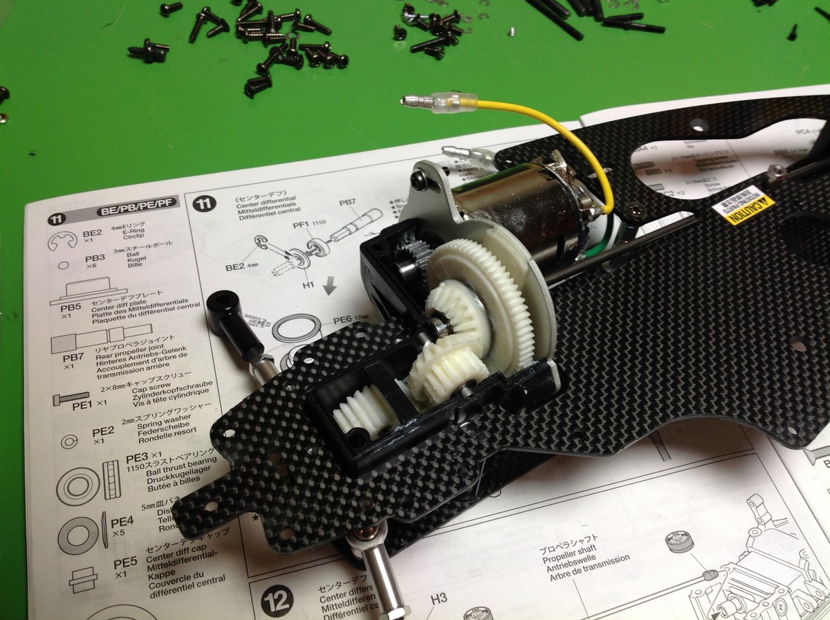
Unlike many 4WD buggies, this one actually has a center differential. This is a ball differential which is integral to the motor spur gear. This does not use a coil spring to adjust the tightness, instead it uses a stack of 5 Belleville springs. The right image shows the center diff installed in the rear gearbox, but at this point there is still no gear to connect to the rear differential. The center drive shaft is just a steel rod with the ends flattened. It is not a hollow tube and it does not have any splines.
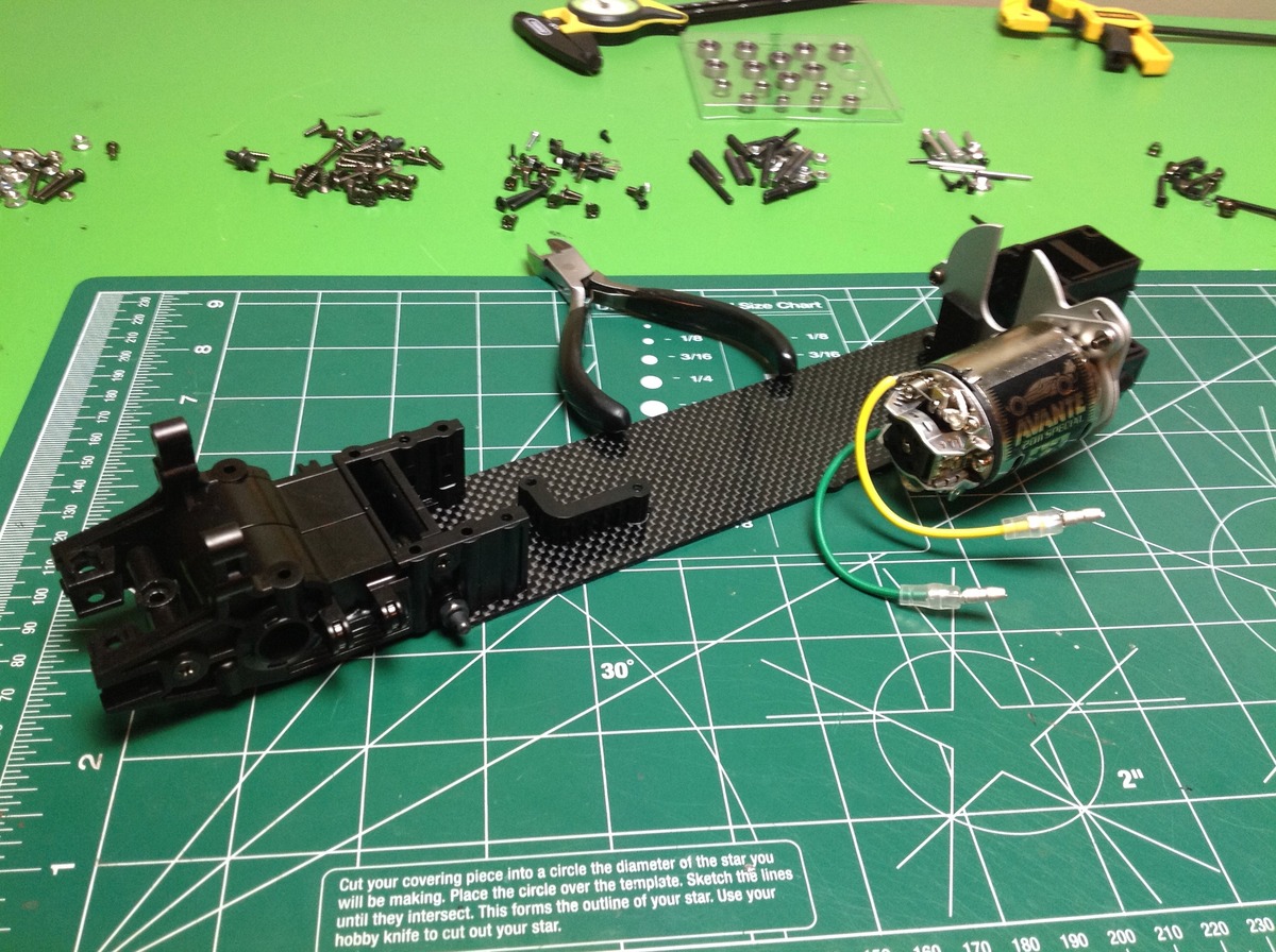
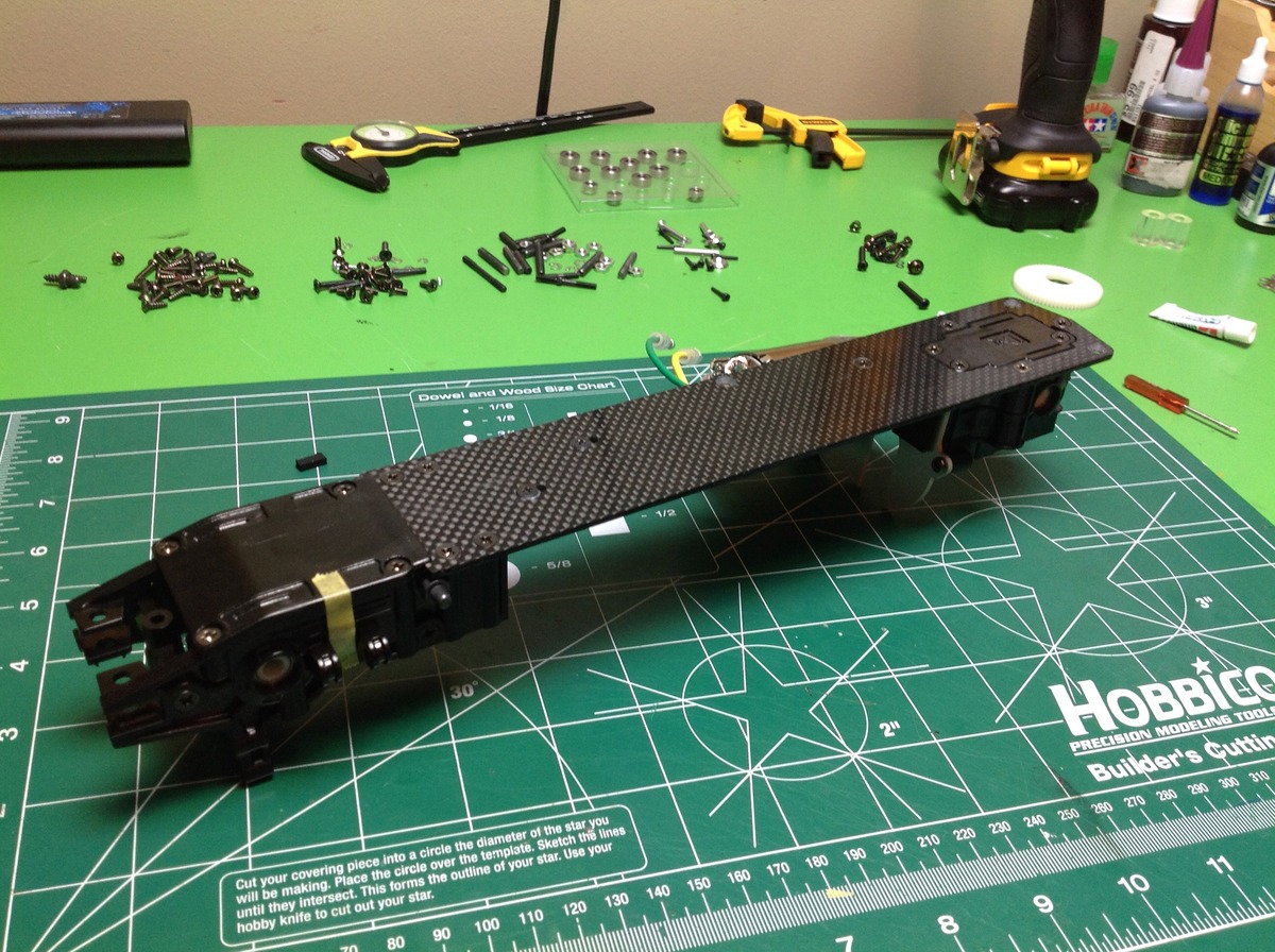
The addition of another carbon plate at the mid-plane completely changes the stiffness of the chassis. Now it is a brick. A really light brick. This plate has plenty of cutouts to accommodate the motor, the center drive shaft, and the later installation of wires.
Time to finish the rear gearbox. One more idler gear completes the rather complex path to the rear axle. There is the pinion:spur stage, a bevel stage, 2 spur stages, and then the differential. Since the rear has one more stage than the front, you'd think this would result in them rotating opposite directions. I was actually a bit worried about this until I saw that they mirrored the direction of the bevel gears to compensate.
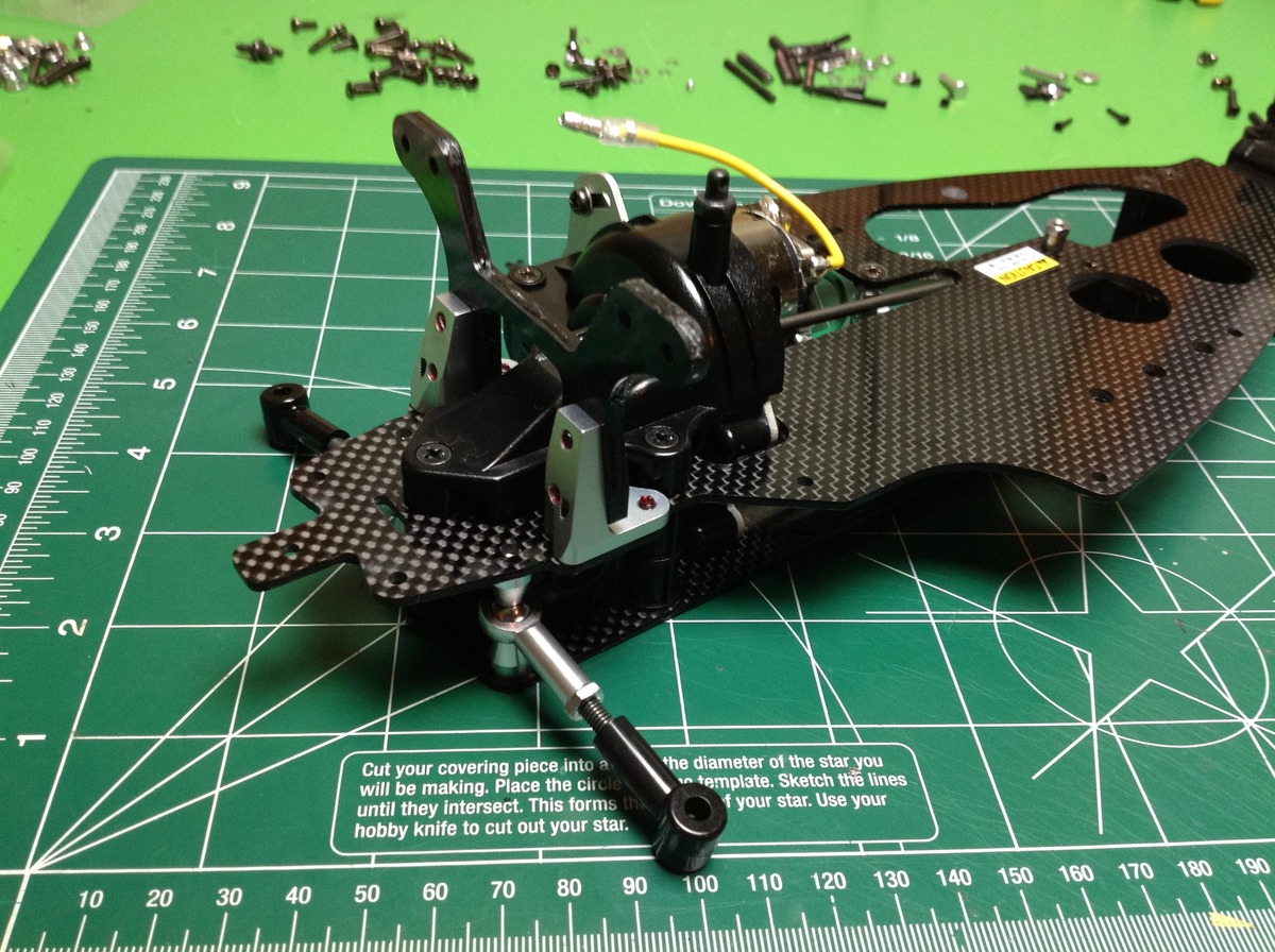

Now we can close out the rear gearbox from above and also install the shock tower and rear bumper. The shock tower is also a carbon plate. You can also see the fine wire sway bar clipped to the chassis.
Building the Suspension
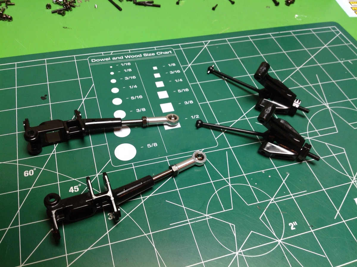
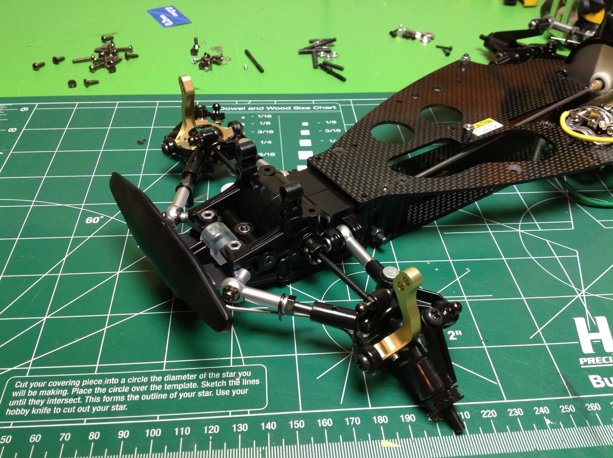
Time to get started on the rather unusual suspension. The links you see on the left are radius arms which are intended primarily to carry thrust loads (power and braking). The vertical hubs are on the right and include the wheel bearings. Note that the nice CVD style axles are new for the 2011 re-release; the original used dog bones. First the radius arms are connected to the rear links we installed earlier and to the mid chassis plate.
After that the vertical hubs are pinned in place, the axles are installed. Installation of the upper rod completes the rear suspension geometry. Altering the length of the upper rod will change the camber while altering the length of the radius arm will change the toe. The sway bars have been attached to clips on the upper arms.
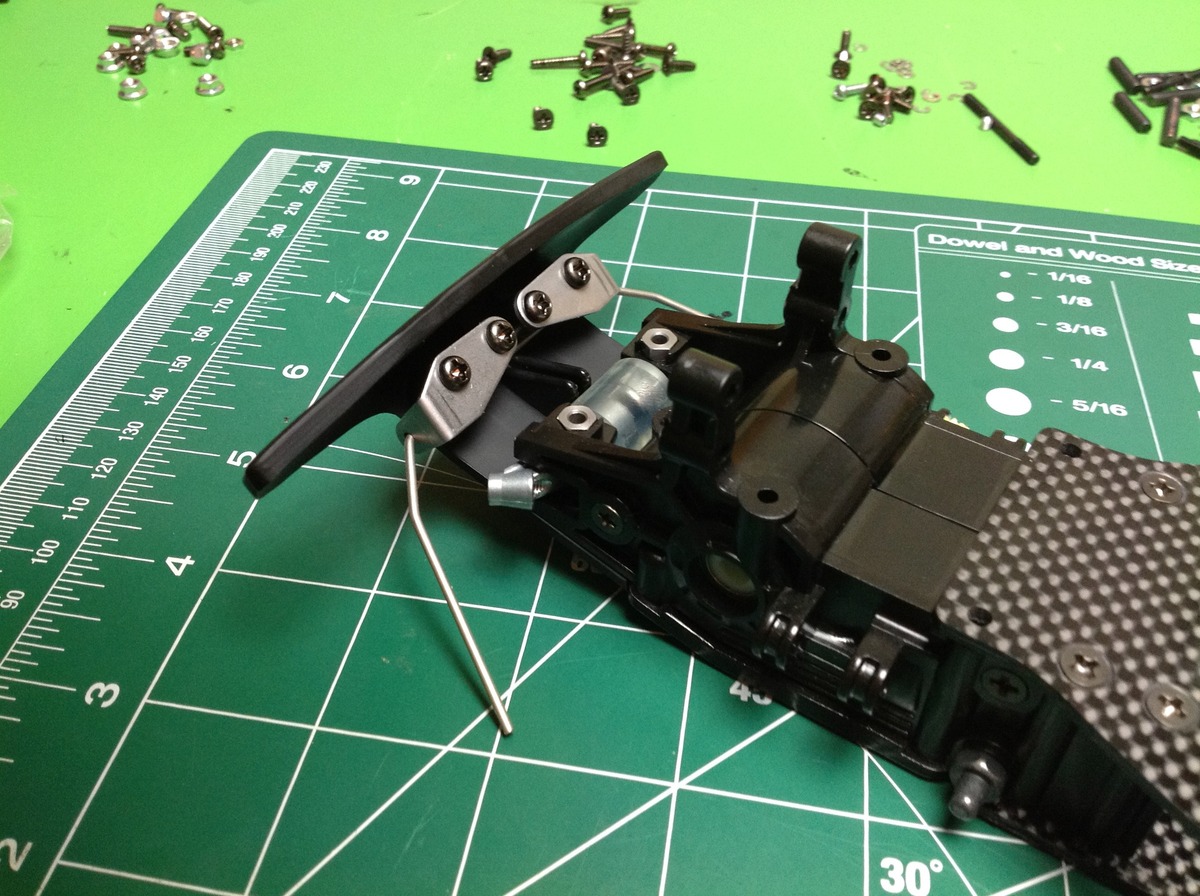
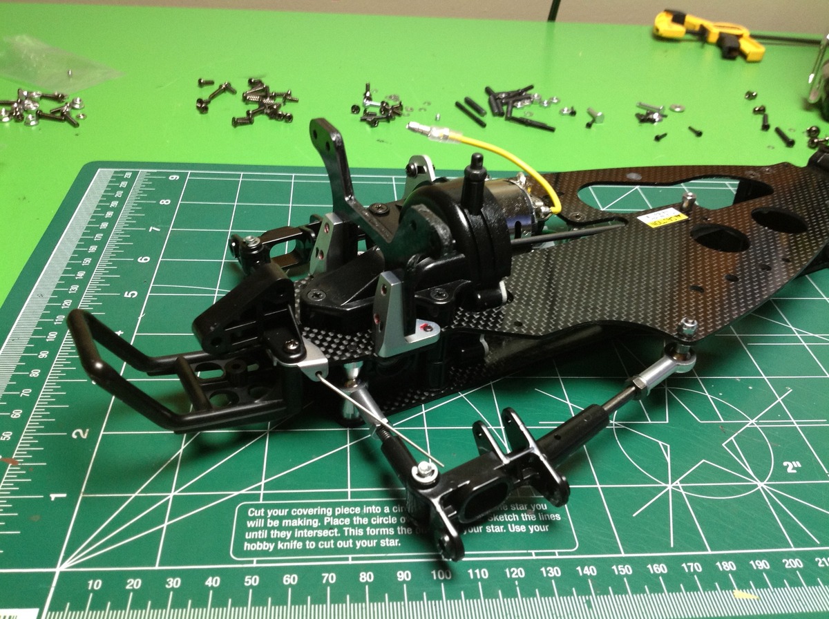
Here the front bumper has been attached along with the sway bar and pivots. You can also see the little silver attachments for the radius arms which pivot in a clear plastic tube. This plastic tube serves as a load relief for front tire impacts.
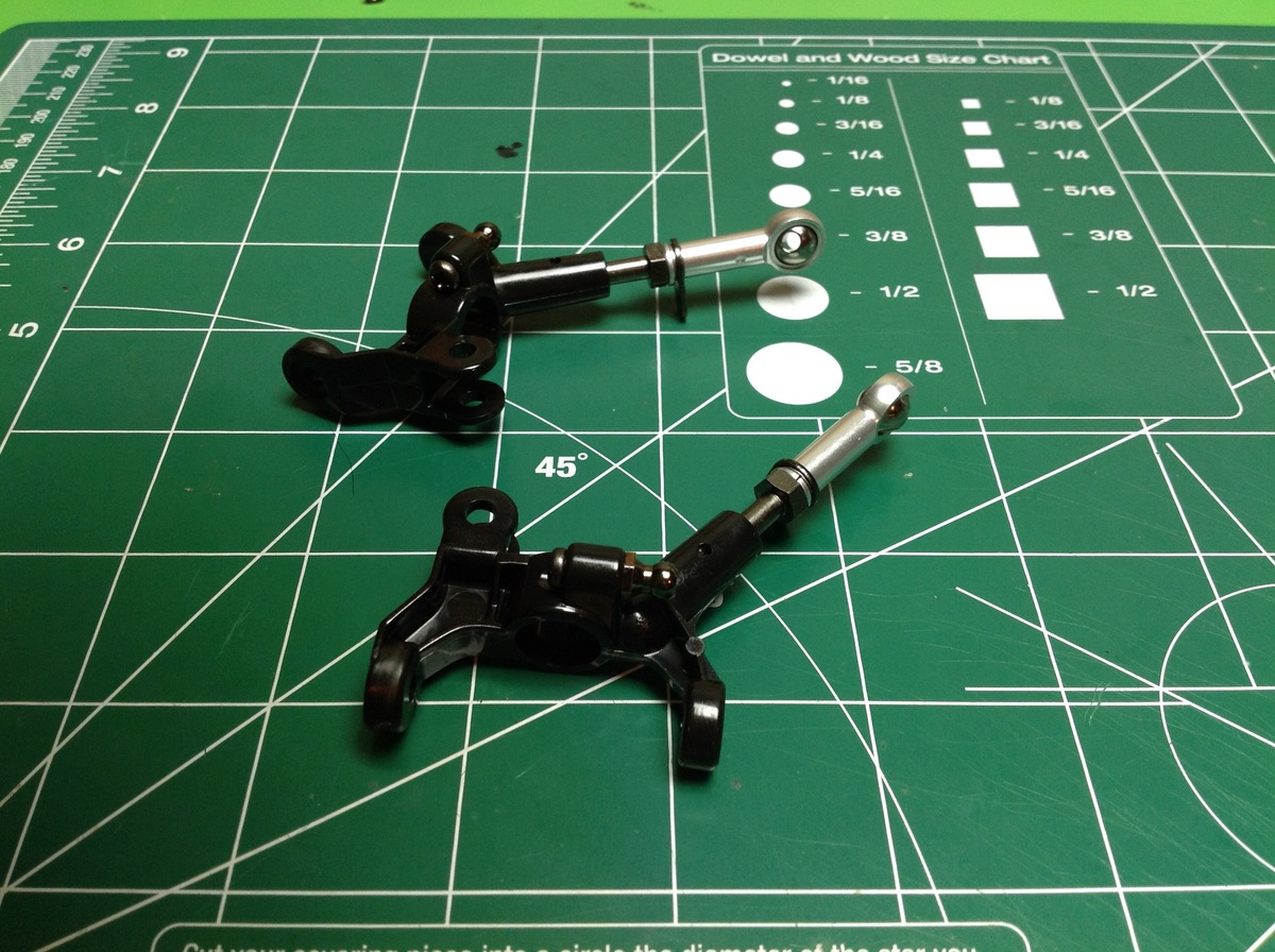
Very unusual front horizontal c-hubs here. These act as lower control arms and the wide stance allows excellent thrust rigidity.
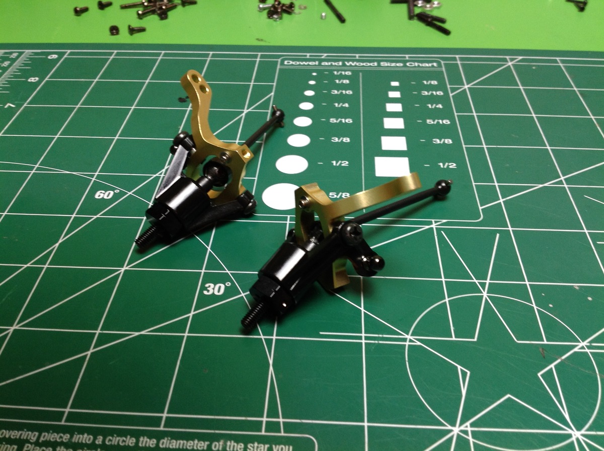
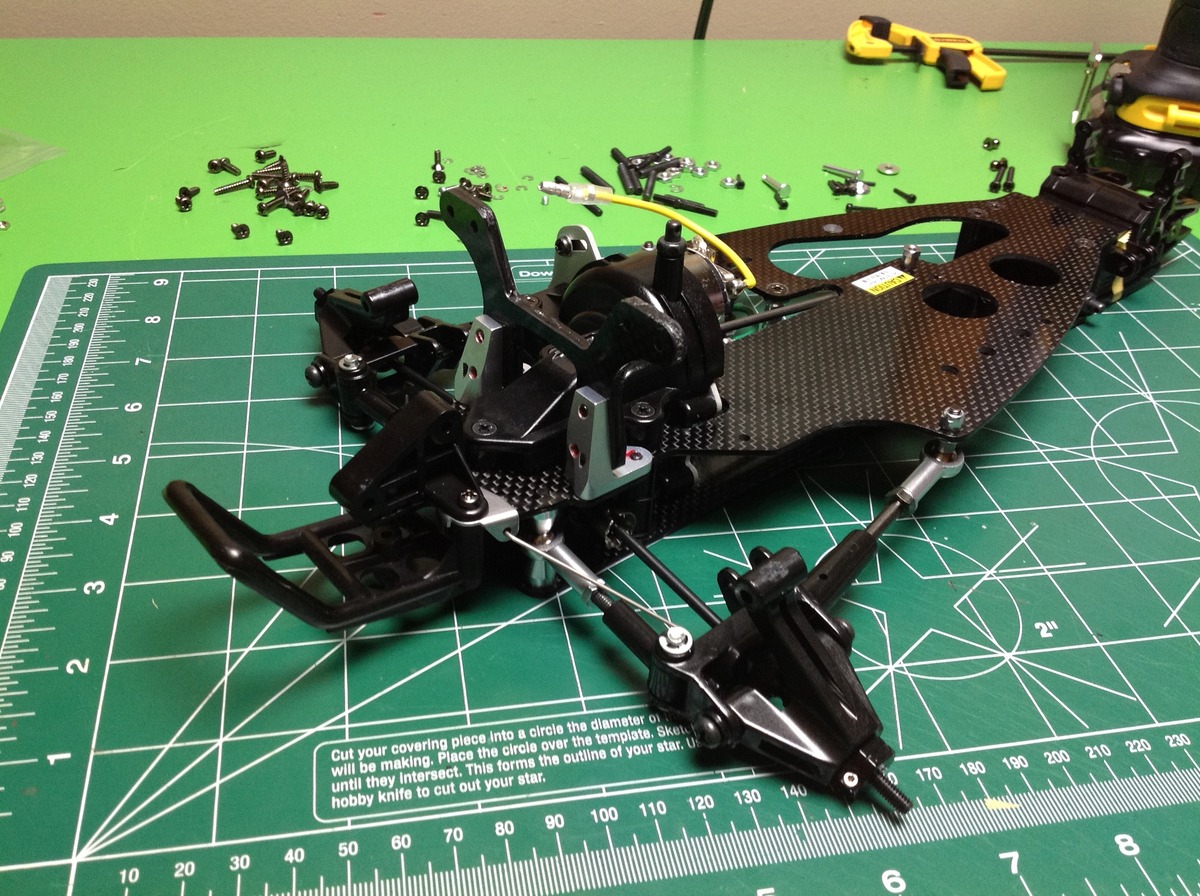
Time for the first cool gold anodized parts. The original cast aluminum uprights were among the most fragile parts of the model and were a real durability problem. The new gold uprights are machined and are greatly strengthened. Here we them as part of the highly complex front steering assembly. In the previous step we saw the horizontal c-hub. The gold upright pins into it and controls the camber pivot. Yet a third part, this time a plastic knuckle, pins into that one and controls the steering (and toe) pivot. Front CV drives are also installed at this point in contrast to universal axles on the original.
I'm not sure what the logic was behind what to make gold and what to make silver. All the rod ends are silver and and so are all the plate components. If all the machined parts were gold, that would make sense but the rear shock tower supports are silver. Somehow it all works and the model ends up looking coherent.
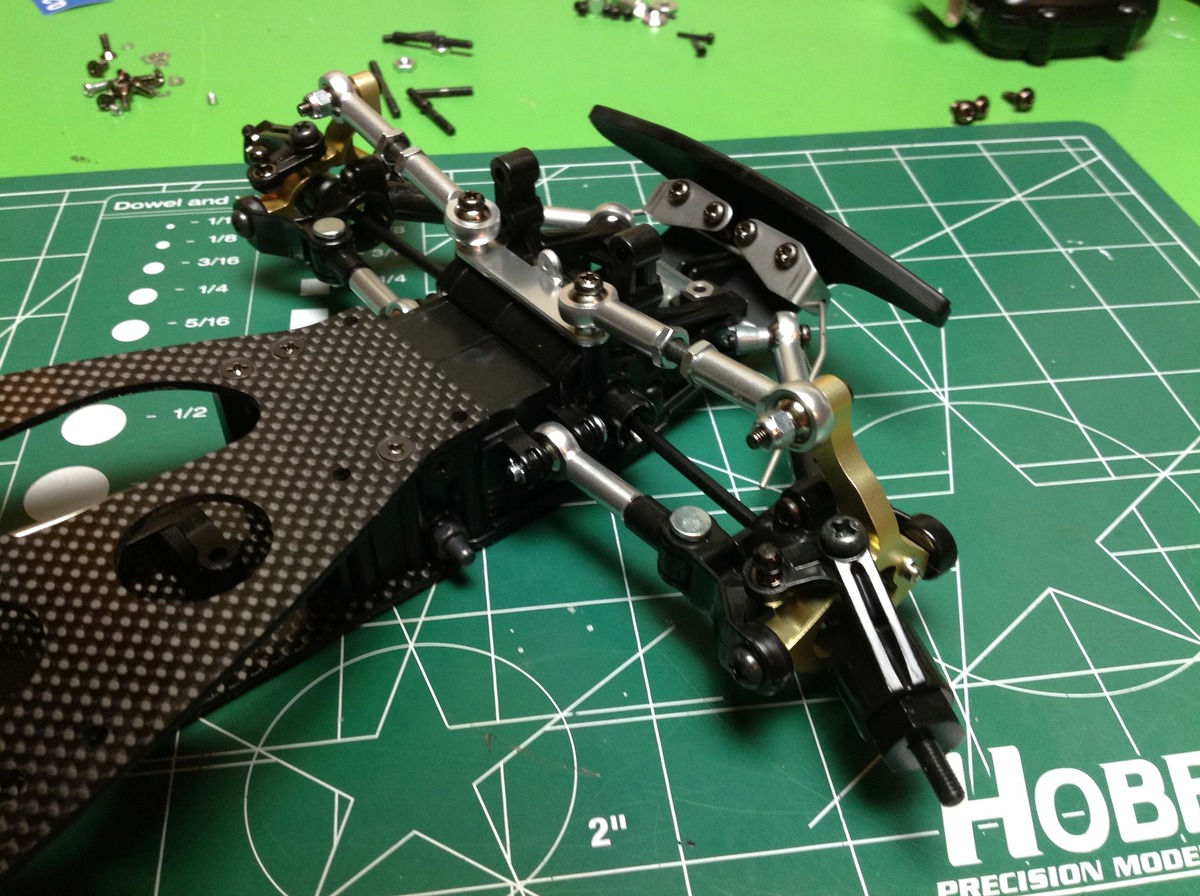
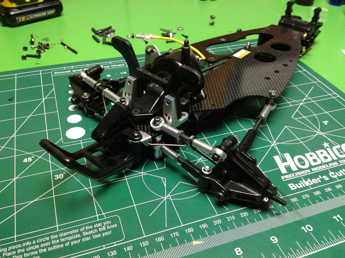
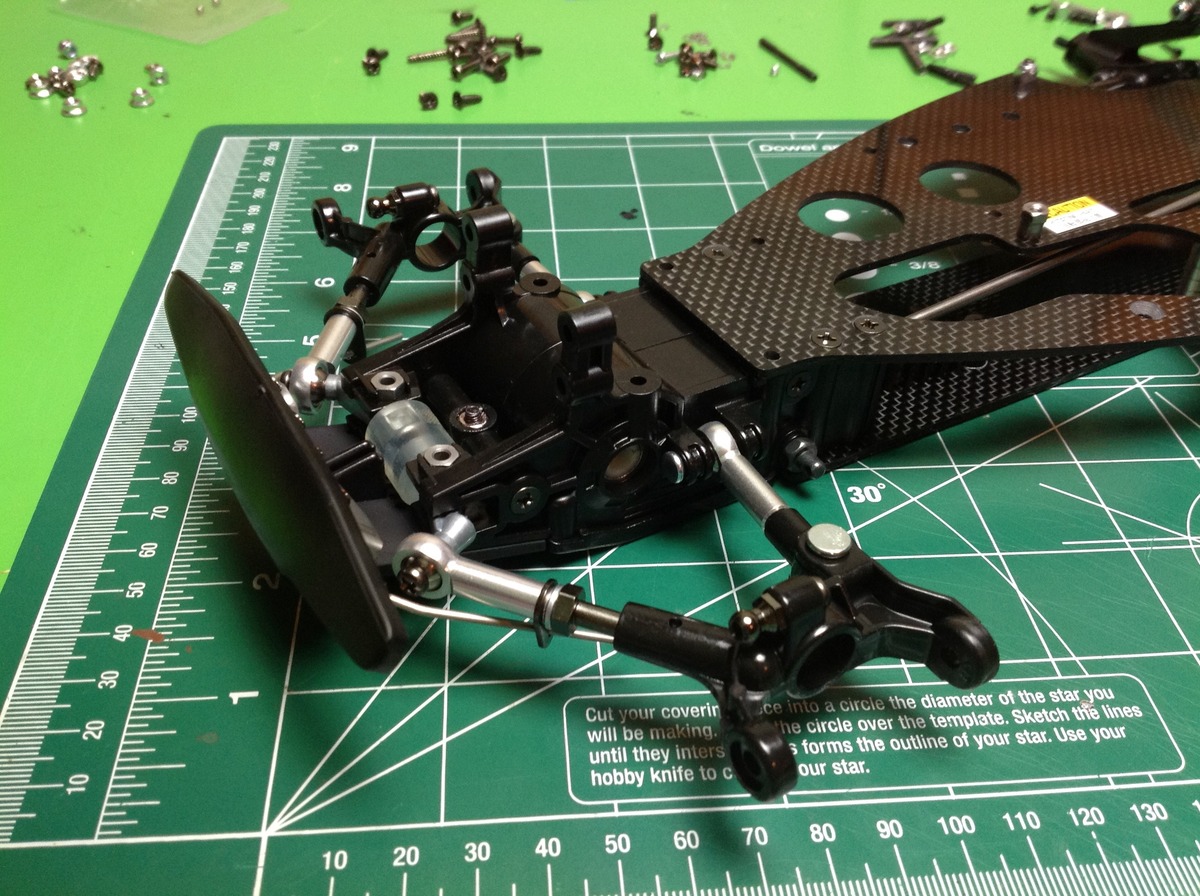
Now the upper arms are connected to the hubs completing the front suspension. Continuing with the trend of being non-traditional comes the steering. A lateral link connects the steering tie rods. That link floats on a 4-bar linkage which pivots at two points on the chassis plate. An L-shaped crank completes a right angle turn allowing the servo attachment to drive longitudinally. It all works fine, but there are a lot of joints and therefore many places for friction or looseness.
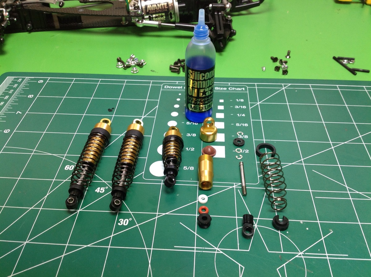
The assembly method of the shocks is pretty standard. There's a volume compensation bladder in the head end and the piston is retained with E-clips. The unusual part is the tapered diameter of the cylinder and matching tapered springs. The kit comes with Tamiya "medium" 600 weight damper oil which seems about right.
At first glance these shocks appear the same as those used on the 1988 original, but there is an important difference. In the original, the rod end seals were swaged into the cylinder and could not be accessed or removed. In the 2011 version, the guide ring and seals are installed with a plastic threaded retainer. The assembly details can be seen in the exploded view above.
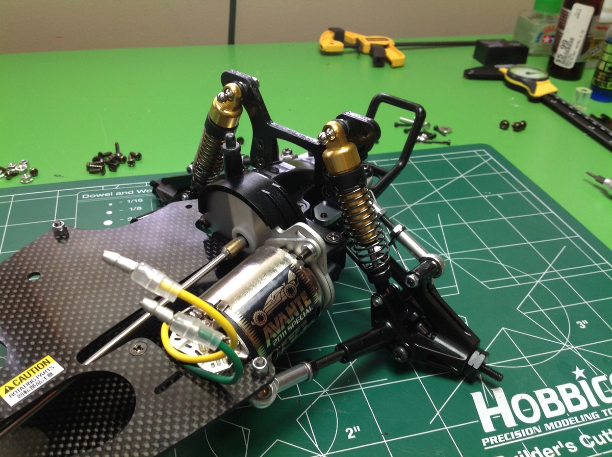
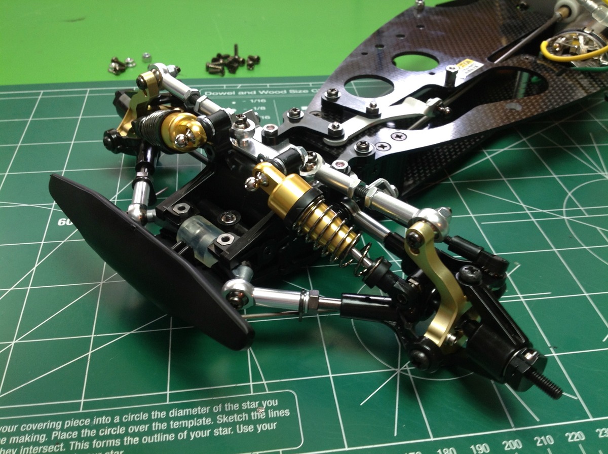
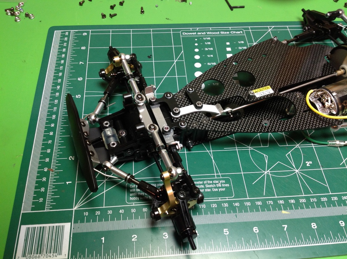
The rear shocks are installed in a pretty standard fashion, but the front shocks face almost totally inboard. This is very good from the point of view of having small frontal area and is also very strong compared to a tall cantilever. This design avoids the tall front shock tower that dominates the look of many buggies and makes the Avante look different. The rear shock tower has been strengthened from the original with a lateral gusset.
Update: I discovered much later that I had the rear arms installed upside down. You can see how the shocks attach above the wheel axis but they should be below. The result is that the rear end sits much lower when built correctly.
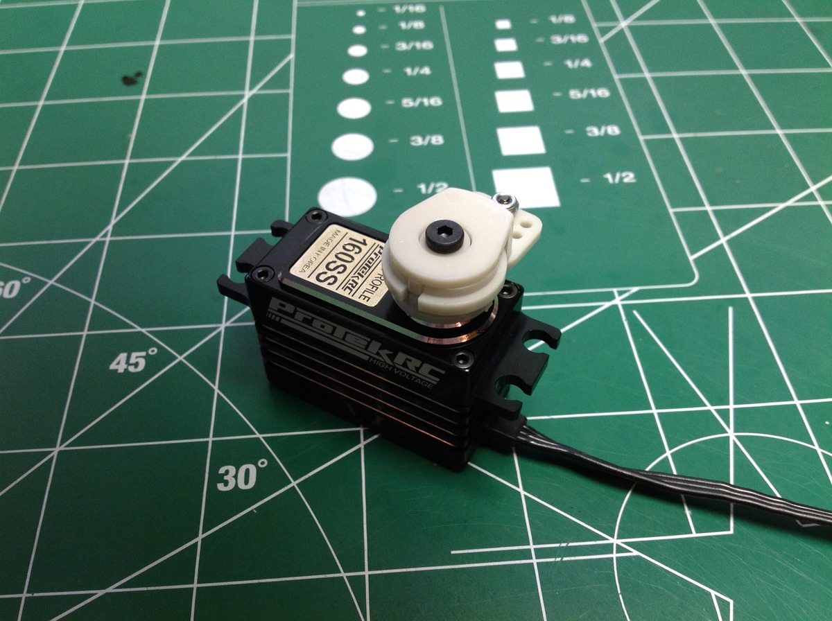
This model is so special that I couldn't just use any old generic servo. I was searching for something with an aluminum case, ideally gold anodized to match. I couldn't find anything that matched, but the Protek 160SS looks really nice and has impressive specs (127 oz-in at 0.05s). After installing it, I also found it to be the quietest servo I have ever used. It is nearly silent. Sadly, once installed it is totally hidden. I actually wish you could see it because it looks so cool.
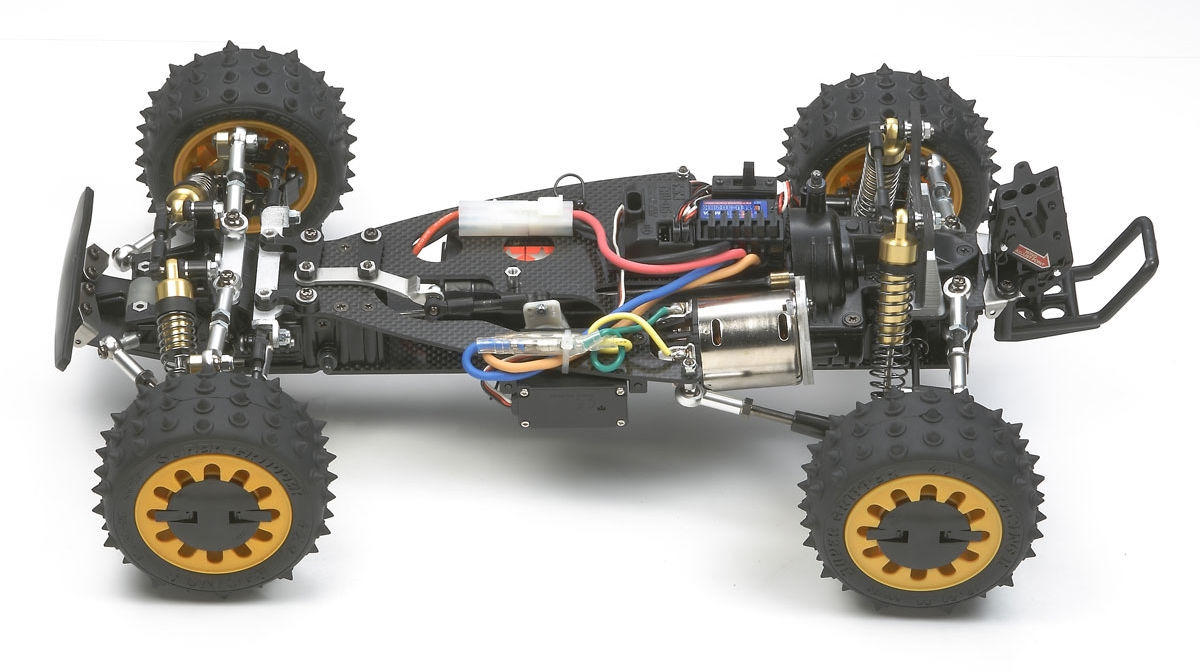
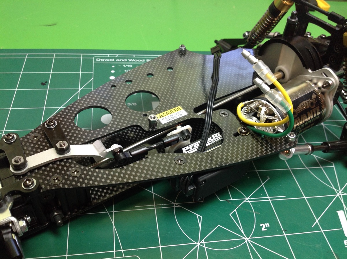
The last step of chassis assembly is installation of the radio gear. I've got a 2 channel Spektrum receiver and a Tamiya TLBE-02s ESC. The battery is installed between the two chassis plates next to the steering servo.
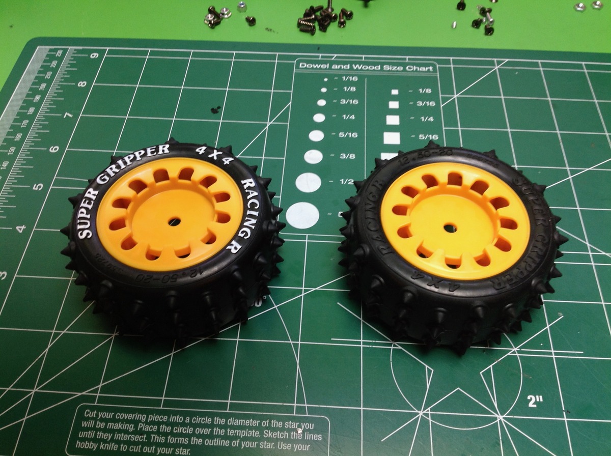
The final touch is the unique cam-loc wheel system. The wheels have a traditional drive hex on the back, but instead of a wheel nut the entire wheel cover is the nut. A pair of links fold out from the cover to be used as levers to tighten the wheel, then you simply fold them into the grooves in the wheel to lock. No tools required. Works really well. I also took the opportunity to use a paint pen to make the tire sidewall lettering white which I think adds a lot of extra character. Unlike many Tamiya cars, this one actually come with tire foams.
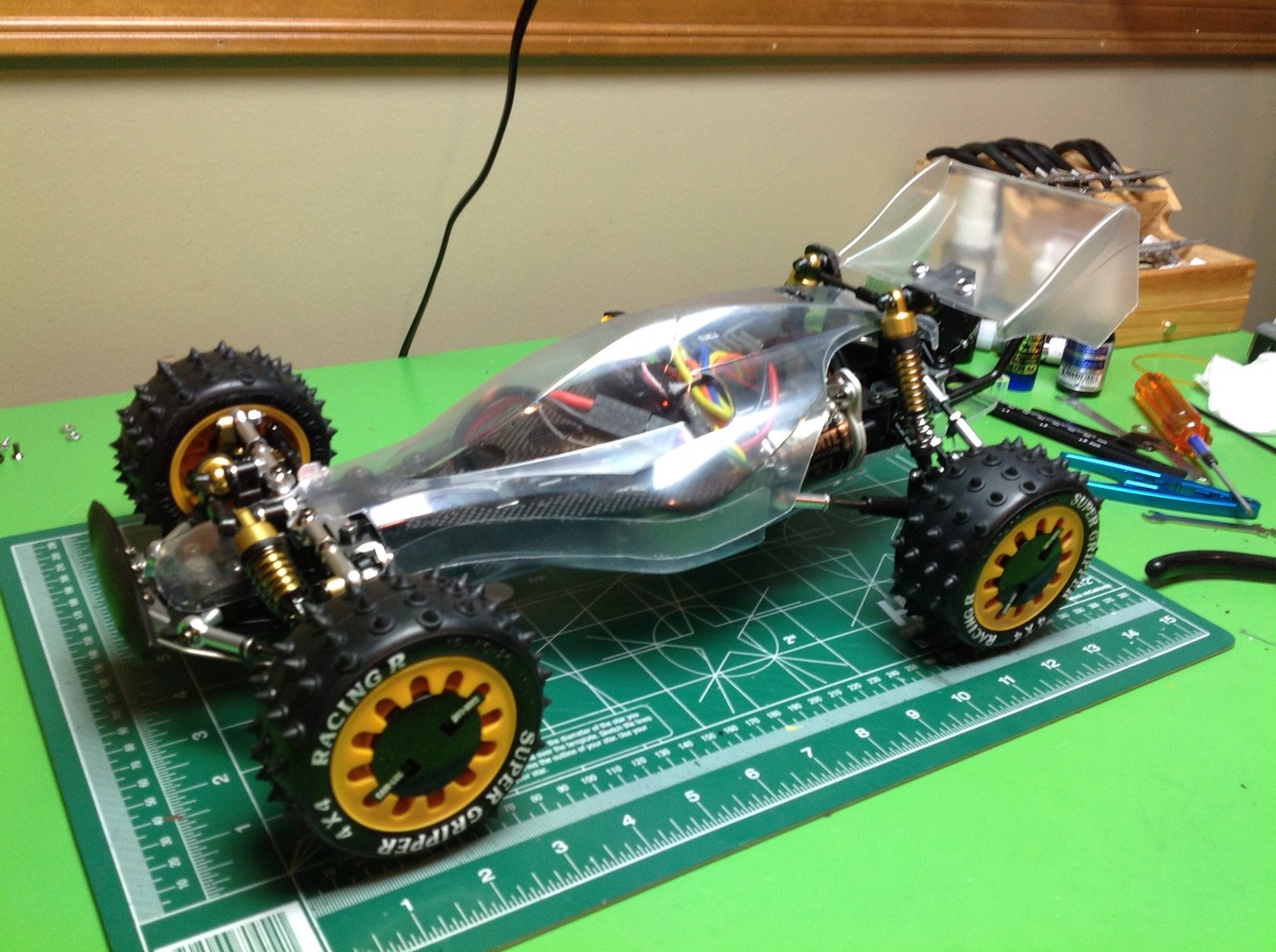
In addition to the clear body and wing, the model comes with a bottom tray. This does a good job of protecting the carbon chassis plates. It swivels down for battery access, but sadly you cannot reach the connector without also removing the upper body. The upper body is hard to remove because the lateral links which connect the shock tower balls are in the way. You need to remove them every time you remove the body.
I painted the model per the box instructions with Metallic Blue. The wing is a little difficult to paint because of the very thin vertical sections. Would be easier with an airbrush that you could get in closer.
Final Photos
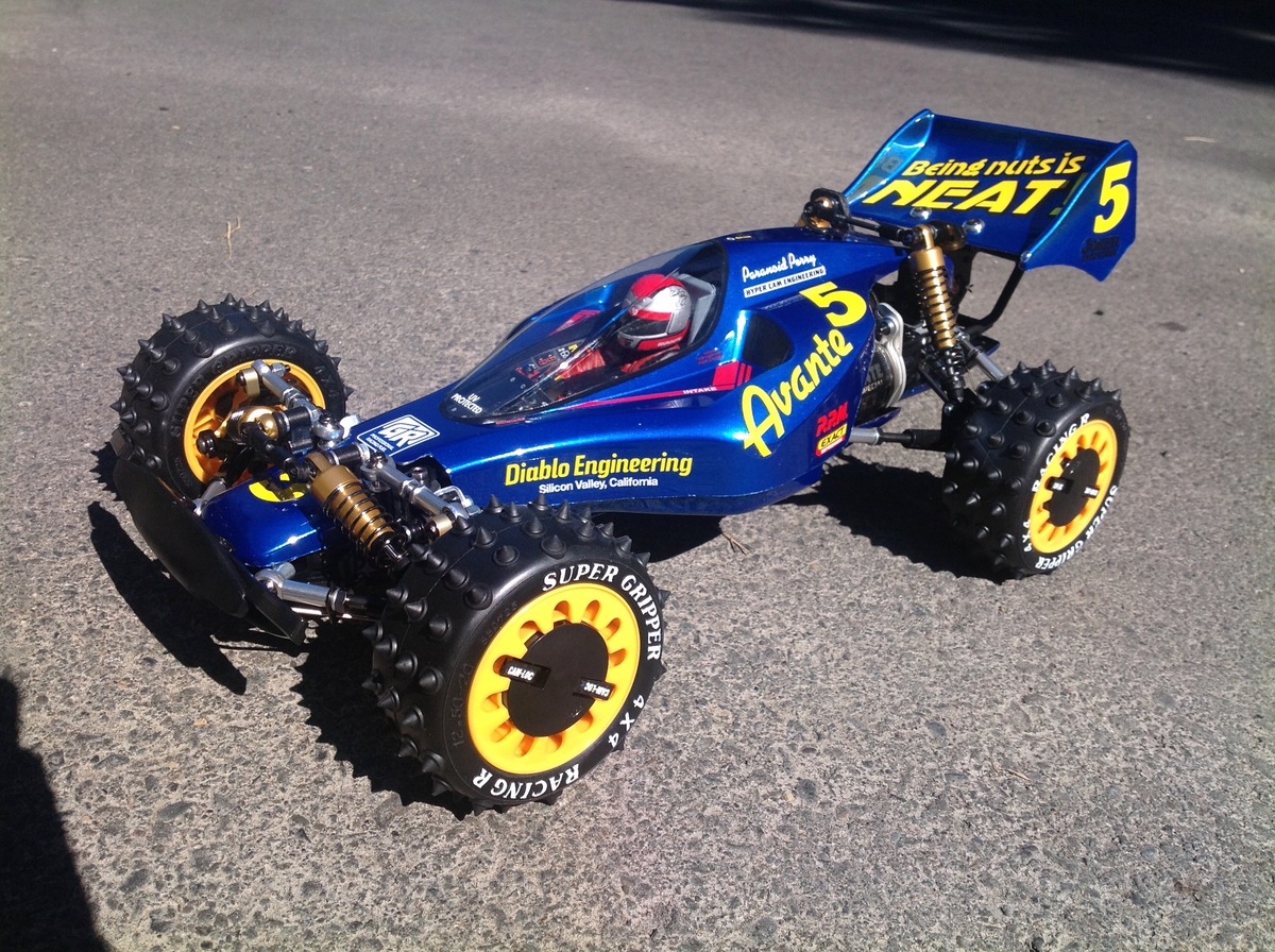
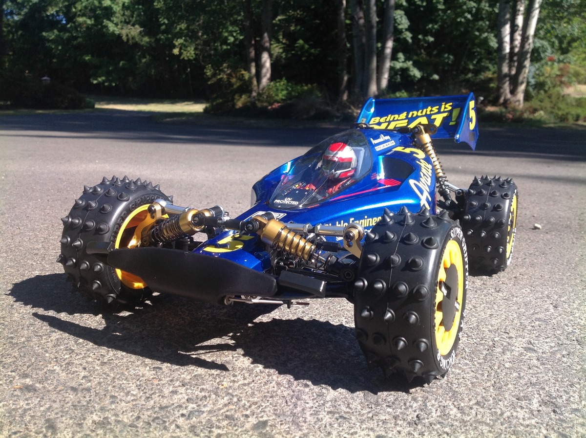
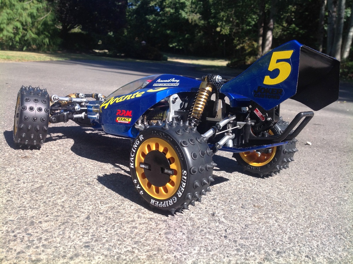
Are there any better looking buggies than this? I'd be hard pressed to come up with one. The styling of the body along with all of the aluminum bling make this one in a million. I like the intakes on the sides. The driver figure is exceptionally detailed as well. Although this is not a scale model of a real vehicle, if you look at the size of the driver then this would be an enormous machine if it were real.
_____________________________
Written by Eric Albrecht
Visit Eric's personal site with lots of build threads.