Preamble
I have a bit of a thing for asymmetric design on radio control transmitters, recalling as it does the look of walkie talkies, the antennas on ghetto blasters (boom boxes), military radio backpacks, satellite phones, the earliest mobile (cell) phones, and even some of the earliest RC transmitters – though it has to be said I wouldn’t include RC toys in that, or modern pistol grip/steerwheel radios, which are uneven by their very nature.
However, asymmetry is a bit of a rare thing in radio gear of the last 40 years, with most manufacturers playing it safe and producing transmitters having mirrored design, with a stick on each side and the antenna, power indicator, and power switch right in the middle. Futaba have often tried something different (antenna on one side or the other, strap on one side, front loading battery compartment & spare crystals holder, servo reversing switches on the front panel) although they seem to always revert to a “safer” design with the next generation of transmitter.
Introduction
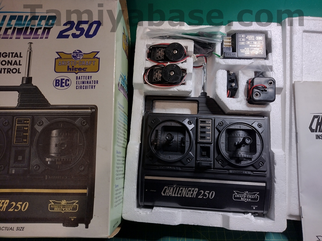
I’d spotted a Hitech Challenger 250 transmitter on eBay & was very interested in it, but then found a boxed, Aristo-Craft branded set instead, for only twice as much ;). It was purported to be unused, but unlike genuinely new sets where every single item is bagged up with the wiring tightly wrapped up, this had the major components unbagged and plugged in.
It must be said that that the asymmetry is limited to the carrying handle being set off to the left- hand side of the case – in all other regards it’s a very conventional looking two-stick radio of the period, even the antenna is still in the middle.
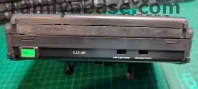
This set is branded “Aristocraft Hitec” – but that appears to be the only difference between it & a “Hitec” unit. On this particular transmitter, the Ni-Cd charging port is fitted to the left side of the case rather than the front panel – but it’s still shown as being on the front on the box and in the manual.
The Polk/Aristocraft/Hitec Connection
Polk’s Model Craft Hobbies (New Jersey, USA) manufactured or imported many hobby items under the “Aristo-Craft” name. Although they were known mostly for their model trains, they also covered RC gear, from the very early “Code-A-matic” single channel set with its hand-size transmitter, to sophisticated multichannel sets, and a number of dual badged Aristocraft Hitec “Challenger” sets.
They also produced some RTR RC cars in the 80s, apparently based on the Marui Samurai: the 2WD Aristocraft Hitec Kangaroo and Koala & 4WD Dolphin buggies, and the Wildebeest truck.
Sadly, Polk closed at the end of 2013.
Unboxing
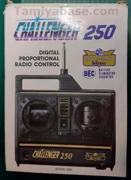
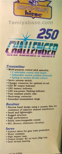
The box is smaller than average for radio gear, it’s a full colour affair with an “actual size” rendering of the transmitter which I suspect is a drawing rather than a photo, or at least a very artfully retouched one that must have looked good next to the hand-crafted box art seen on most RC kits of the time. One side gives technical information in English, the other in French.
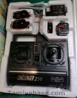
Inside is a conventional expanded polystyrene foam clamshell, the top half of which has a recess on the outside which doesn’t entirely contain the manual.
The Transmitter
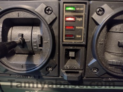
The transmitter has a 3 red LEDs for battery power indication, and a rather superfluous green “on air” LED. Trim controls are mechanical, and the throttle stick has an optional 60/40 (or so) split switch for IC powered cars.
The transmitter is really quite small, I couldn’t get more than 3 fingers through the handle – and probably none at all if I was wearing any sort of gloves, and the antenna is quite thin and wobbly. Despite my thumbs feeling oddly close together, I found it uncomfortable to use due to the distance between the tips of the sticks and the back of the case. It might be better if you have bigger hands, but then I suspect the closeness of the sticks will feel even weirder. According to the box the stick length is selectable between two lengths so you might think I have the longer setting on, but no – the spare caps in the box are even longer. I also can’t see how to change them – I feel like any more force is going to break something.
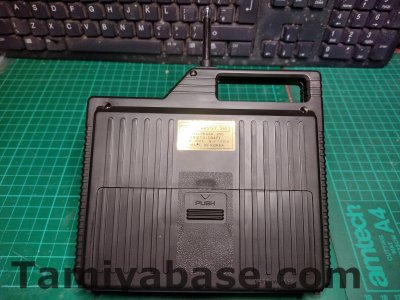
The power switch is deeply recessed & quite difficult to access, and the battery cover is very loose until you put batteries in it, in which case it won’t close properly.
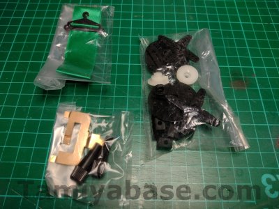
It looks ok from 3 or 4 feet away, but up close it seems a bit cheap. There’s a loop for attaching a lanyard (or “neck strap” as it’s referred to in the manual), but none is provided. An almost implausibly green antenna pennant is included.
Servos & Receiver
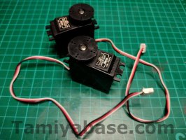
A pair of HS-402X servos are included, variously listed as being 3kg or 3.2kg units. They’re made in Korea (South, no doubt) as is everything else apart from the 4x AA holder, which is Taiwanese & presumably bought in.
The servos sound scratchy, although one is better than the other. Round horns were a bit old hat by this point, but there is a pair of conventional + shape horns in a bag of bits, which also includes two even bigger round horns, what looks like two Tamiya compatible servo saver bases, hard and rubber mounts.
The plugs are conventional other than being moulded in white and much shorter than usual. The pinout is:
- Earth (ground, or negative, -ve) Black
- Power (or positive, +ve) Red
- Signal White
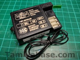
The HP-2RNB receiver is nothing notable compared to anyone else’s of the time and is BEC capable.
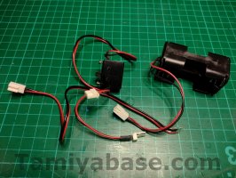
The switch loom has a plug for the 4xAA battery holder to plug into, but both are an odd size, looking like a 2-pin fan connector but smaller, and longer. If you want to take advantage of the BEC function, there’s an additional lead – but you’ll have to solder in on to your MSC or cut the JST plug off the flying lead that were standard by this point as far as I know & splice it in.
There’s an 8-page manual (although page one is completely blank) that does impart some useful information, but seems to spend a lot of time focussing on the wrong things – did anyone in 1985 really need a list of all the 27, 75 and 75mhz frequencies, for example? It also looks very dated – if it wasn’t for the references to BEC it could be from a decade earlier.
n.b this should be available in the TB database by the time you read this
Amateur Archaeology
BEC (battery eliminator circuitry, i.e. removing the requirement for the 4xAA battery holder powering the radio gear on the car, instead dropping the main drive battery voltage to a safe level) appeared mid 1984 in the form of an additional 2-wire cable and JST type connector on the MSC (mechanical speed control) and a small circuit board on top of the car radio on/off swich.
It was quickly superseded by circuitry built into the receiver itself, and that’s what we have here.
Servo reversing switches were first seen on mass market Futaba sets around the same time, but didn’t appear on an Acoms set (specifically the Technidrive, aka mk.iv) until 1987.
Visually, it seems very similar to the Acoms mk.iii TX (1984) and to the much earlier (and more expensive) Futaba “L” series units.
The servo reversing switches being on the base of the transmitter is not unusual, but the frequency crystal also being there is a little odd. They’re often hidden away under a cover or on the back, an artefact of the official position in the USA being that you weren’t allowed to change frequency on a transmitter without inspection/recertification. This seems a little odd when the crystal has been on the front of Acoms sets since their first in 1978/9.
The presence of a frequency pennant can also place a radio set in time – they’d gone from new sets by 1987.
No year is mentioned anywhere on the box, components or manual, but from looking at the features we can probably say the Challenger 250 comes from around 1985. In terms of Tamiya cars, that means the 58047 Hotshot onwards – although given that kits were in production for some time, as were radio sets, the Challenger 250 could be equally at home in slightly earlier cars, such as
Overall
The Aristocraft Hitec Challenger 250 is well specified for a set from 1985, at the time I think you’d probably be looking at the brown, first generation Futaba Attack R which also had servo reversing switches or the Acoms mk.iii which didn’t (but you could turn the gimbals around 180 degrees) as alternatives. I have a soft sport for the Acoms despite its shortcomings, and you can’t deny the quality of the Futaba, but I don’t think it stands up very well against them, and the attempt at a quirky design is a bit half hearted and doesn’t really add anything.
Getting on for nearly 40 years later, exact years aren’t so important when it comes to matching radio gear to a car – for a 1984 car I’d choose this over the more “correct” Futaba Medallion 2 (mk.ii) or Acoms mk.ii any day.
By the same token, for a 1987 car I’d quickly look past a new Challenger 250 to get a used Acoms Technidrive (“mk.iv”) or chrome Futaba New Attack R set.
The non-standard plugs may be a bit of an issue when it comes to compatibility with other makes.
On the plus side, the 50 GBP (posted) I paid for this plausibly “new” set was way less than anything “popular” from before, during or after the same period in a similar condition.
Overall, 3 out of 6 – and it only avoids a two on grounds of price. It’ll do the job and looks correct for a car from 1985 – but I can’t see it being comfortable in anyone’s hands, adult or youngster.

In fact, I can’t help feeling it’d be best in the hands of a Sasquatch who wants a tiny transmitter to exaggerate their size for comedic effect. Witches with extremely long bony fingers may also like it - at least they’ll be able to turn the transmitter on and off.
__________________________
Written by TB member Jonny Retro


