

This design is based very, very loosely on the Ford Y-block engine from the 1950s - I say "loosely" because although there are reference books out there dedicated to the engine, I worked from images I found for free on Google (mainly from a single photo of a modified engine) and didn't make any reference to dimensions at all, just judged it by eye. As I read that back it sounds very slapdash - but it all worked out ok.
I also use the word "simple" advisedly, because the part count is quite high (230 bits of styrene, 8 bits of wire, plus seven screws & one rubber band) and the description of how to build it is very long at over 7,000 words. However, several areas of the engine have been vastly simplified, abbreviated or omitted all together - a full on scale replica of the 1:1 engine would have been an order of magnitude more complicated. Replicating the internal working parts, even more so.
Those figures shouldn't be intimidating - if you built the example objects in earlier instalments, they totalled around 150 parts, and I'm sure I was at least as verbose ;)
The main idea here is to show how basic structures (as described in previous instalments), along with layering & details can fit together to make a much more complicated scale model.
I built this engine with the intention of fitting it in the engine bay of a Tamiya 1:12 "Midnight Pumpkin" Ford F100 pickup, but it's a very tight fit in there so I think it could also pass as the powerplant for a larger 1:10 truck. Finished dimensions are approximately 130mm front to back, 85mm wide and 80mm tall so you might need to make modifications in order to accommodate it.
The bulk of this article is a detailed description of the construction steps, and I've also drawn up plans* if you want to follow along at home, but the main idea is get you building & take it as far as you want to. There are obvious areas for increasing the level of detail (carburettor- including linkages and throttle/choke cables, details on the gearbox, better exhaust pipes etc), you could also apply the design elements to make a straight six of similar vintage, or make a more modern V8 (by relocating the spark plugs, reducing the angle of the V and the distance between the banks of cylinders). V6s and inline fours too.
The real trick is to look at a complex 1:1 object & mentally break it down into sections (I'd suggest box like) that you can make easily. For instance, not knowing where to start with this, I thought about how big I wanted the main section of the engine to be (about 53mm front to back on the crankcase, not including sticky out bits), that implied that the heads would be a bit shorter (50mm) and a proportionate width on the tops (16mm, judging by eye) - and this in turn implied that the valve covers would have to be smaller still (46mm x 12mm) to allow for the bottom lip detail - so that's where I started - with one of the outermost structures, not the one you might think of as being the core.
* Note on the Plans: Although it's theoretically possible to cut parts out directly from the plans, I intended them more as a "sanity check" for parts made by measurement from reference to the text: I'd recommend cutting each bit out as described, and if it doesn't look very similar to the outline on the plan, then something has gone wrong ...
See the bottom of this article for links to download plans.
Build Time & Costs
I'd estimate the likely time needed to build & paint this at around 50 hours, spread across at least three weeks - meaning that I wouldn't be surprised if it took twice as many hours, and many, many more weeks - but I'd be impressed if you could do it in less.
Regarding costs, if you're only ever going to build this one thing, buying the styrene sheet and forms (let alone the tools) simply doesn't make economic sense. If on the other hand, you want to make several engines, or lots of other, yet to be imagined things then the unit cost will come way, way down.
You Will Need...
Likely tools & materials have been listed in previous parts and you can make your own choices, this is simply what I used on this build. As I've rated this an "intermediate" build I didn't try to skimp on the range of materials or tools I used - but I did avoid using a lathe at any point. Paints are just suggestions - read the section on painting near the end & work out your own alternatives and/or simplifications.
Tools:
- Craft knife / scalpel, cutting mat, ruler, pencils for marking out;
- Rotary leather punch;
- 0.8mm drill bit & Archimedes drill;
- 1.2mm, 1.5mm, 3, 3.2, 4.5, & 5.5mm drill bits & a suitable drill;
- Rubber profile cutters;
- Round needle file, medium flat file;
- Dremel with medium spherical burr, medium straight burr, small and large sanding drums;
- Engineers square (a small one);
- Circle template and/or compass cutter(s);
- Hot air gun.
Materials:
- 0.25mm, 0.5mm, 0.75mm, 1mm, 1.5mm, & 2mm styrene sheet;
- Poly glue (the regular kind that'll be familiar of you even made a plastic kit in the past);
- Liquid glue (e.g. EMA Plastic Weld, or bulk Dichloromethane) + brushes to apply it;
- Cyanoacrylate (Superglue);
- M2 screws - eight short ones (e.g. 4mm);
- M3 screws - three off, around 10mm long;
- Coarse, medium & fine wet & dry paper (e.g. 120, 400 and 1200 grit);
- Filler (e.g. Squadron White putty);
- Epoxy putty (e.g. Milliput white);
- 1 metre of 7/0.20 instrument wire;
- Tamiya 10mm masking tape;
- Fine metal mesh;
- 2.5mm black heatshrink tubing;
- Styrene forms:
- .080" x .080" (2mm) square strip (Evergreen #164);
- .125" x .125" (3.2mm) square strip (#186);
- .100" (2.5mm) round rod (#213);
- 1/16" (1.6mm) round rod (#222);
- 1/8" (3.2mm) round tube (#224);
- 5/32" (4mm) round tube (#225);
- 7/32" (5.5mm) round tube (#227);
- 9/32" (7.1mm) round tube (#229);
- 11/32" (8.7mm) round tube (#231);
- 7/16" (11.1mm) round tube (#234);
- 1/2" (12.7mm) round tube (#236);
- Paints:
- Acrylic primer, red and silver aerosols (e.g. Hycote White Plastic Primer, VW Mars Red, and "Aluminium Coat");
- Tamiya X-6 Orange;
- X-11 Chrome Silver;
- X-21 Flat Base;
- X-31 Titanium Gold (or mix XF-16 Flat Aluminum & X-26 Clear Orange);
- XF-3 Flat Yellow;
- XF-2 Flat White;
- XF-9 Hull Red;
- XF-16 Flat Aluminum;
- XF-52 Flat Earth;
- XF-56 Metallic Grey;
- XF-69 NATO Black;
- XF-85 Rubber Black;
- Humbrol #113 Rust (or mix Tamiya XF-23 Light Blue & XF-9 Hull Red).
Construction:
001 Valve Covers:
- Cut 12mm and 5mm strips from 2mm sheet;
- Cut four 46mm long pieces from the 12mm width for the bases & tops;
- Cut four 12mm long pieces and four 42mm long pieces from the 5mm width for the ends & sides (see image 001);
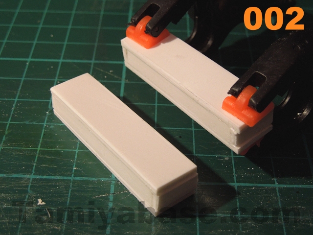
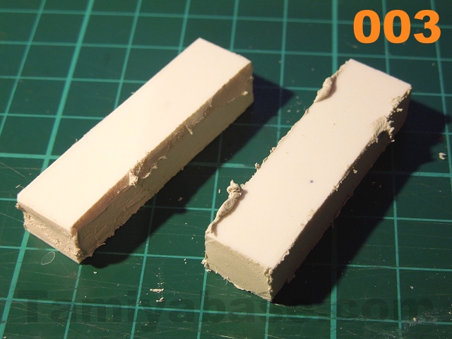
- Sand faces flat & bond together, clamp/tape if necessary and allow to set (see image 002). Add a smear of filler to all the joints (see image 003), and allow time for that to set;
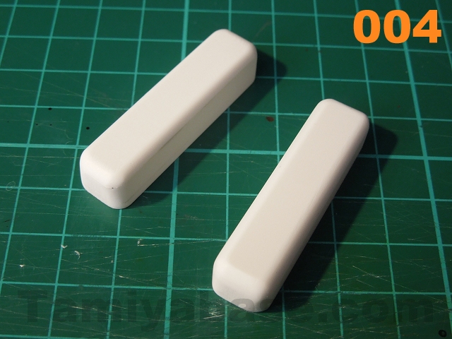
- Using wet sanding (see pt.3), heavily radius the edges (apart from those on the bottom face).Start with a rough grit of wet & dry paper (e.g. 120) & finish off with medium & fine grades (e.g. 400 & 1200) (see image 004);
- Cut a 1mm wide strip from 1mm sheet & use that to form a lip on the bottom of the part;
- Use a leather punch to cut four 4.5mm discs from 0.5mm sheet & bond at appropriate points on the top. Drill a 1.5mm hole through the centre of those & fit M2 screws;
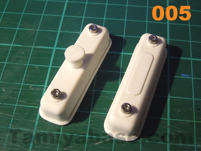
- Add further details if you wish - I've added a simple panel (5mm x 20mm strip of 0.5mm sheet with rounded edges (I may add a transfer later) on the top of one side, and an oil filler tube (7/32" tube) & cap (square cut from 2mm sheet & sanded to 8mm round) on the other (see image 005). You could also use a scriber and/or try a series of strips to simulate ribbing.
 |
 |
 |
 |
Valve Cover Gaskets:
Old engines tend to have fat cork gaskets in low pressure areas, so draw round the completed valve covers on to 1mm styrene, cut out & sand edges (image 005). Don't glue them on yet - they'll be much easier to paint if they're left separate.

002 Heads:
- Cut 16mm and 23mm wide strips from 1mm sheet, plus 10mm and 12mm strips from 1.5mm sheet;
- Cut two 50mm long pieces from each of the 16mm and 23mm wide strips to form the tops & bottoms of the heads;
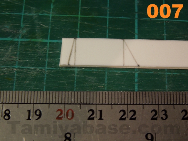
- Cut four ends from the 10mm strip, noting the shape - it's basically a 16mm x 10mm rectangle, but with an extra 2mm on one lower corner, and 5mm extra on the other (see image 007);
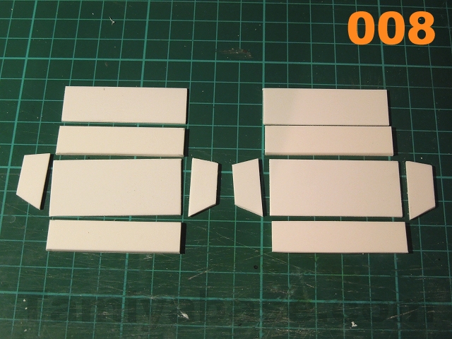
- Cut four 47mm long pieces from the 12mm strip - these will form the sides (see image 008);
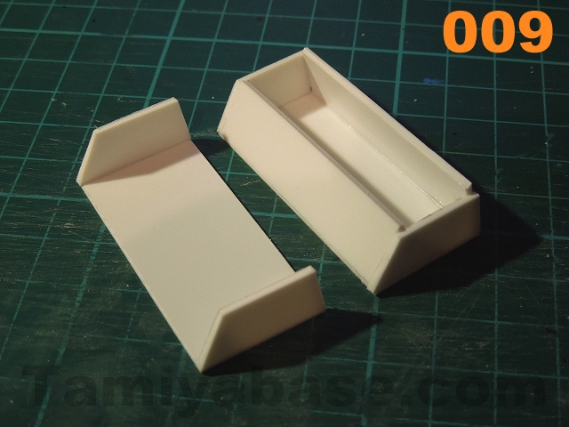
- Fit the ends to the bases, the sides need the bottom edges sanding to the correct angle before fitting. Once all the parts are set, you can make the top edges even with the sides before fitting the tops (see image 009);
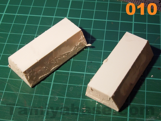
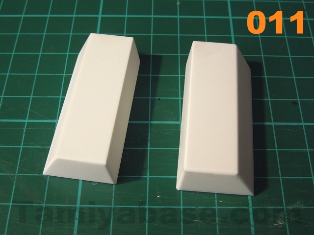
- Fill all the joints (see image 010) & sand back. The edges don't need to be radiused, but you should break the sharp edges a little (see image 011).
 |
 |
 |
 |
003 Spark Plugs:
These are optional - but the HT leads add a lot of detail for not much hassle, and the location (under the exhaust manifolds in this case) can also give a sense of the age of the engine. Assuming you do want to go to the trouble, the first thing to do is make somewhere for them to go:
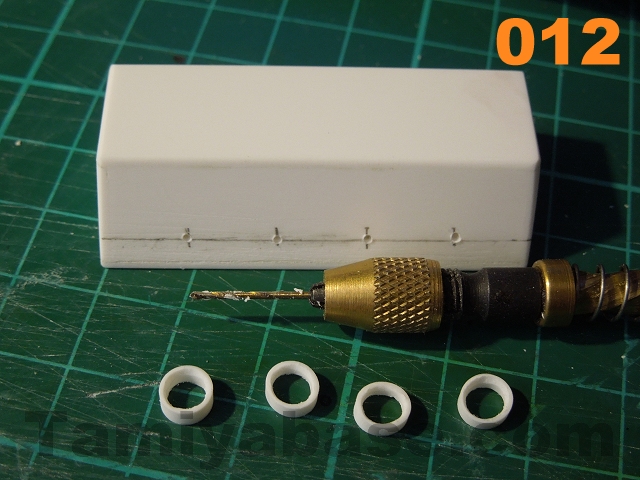
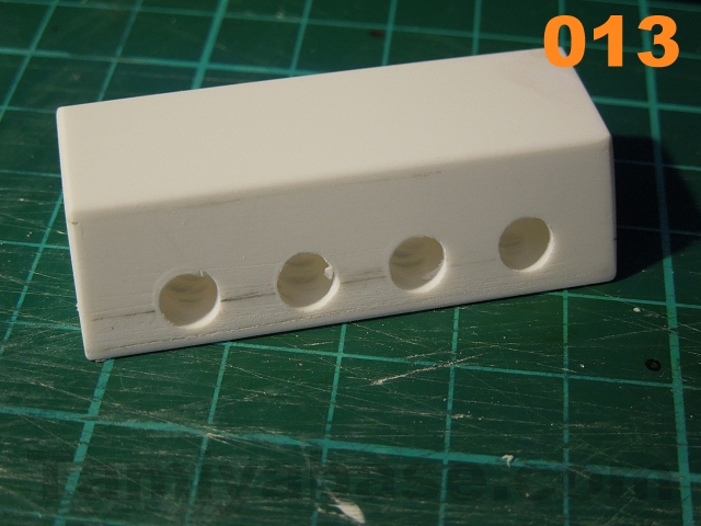
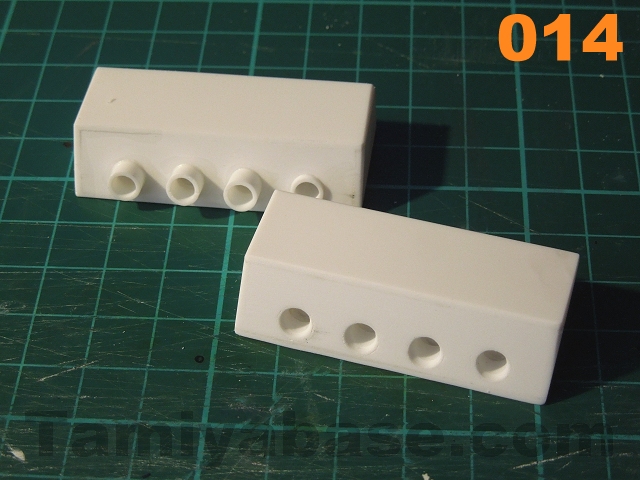
- Mark a line 4mm up from the bottom of the wider side on the heads, and mark at 10, 20, 30 and 40mm - these will be the drill points for the plug holes. Start small & carefully work up - I started with a 0.8mm bit in an Archimedes drill and worked up to 5.5mm in a battery drill (see images 012 and 013);
- Cut eight short lengths (c.6 to 8mm) of 7/32" OD tube, sanding a slight taper on one end, fit each of these to the above holes, tweaking then angles if necessary with a length of 5/32" tube. Bond the 7/32" tube to the heads, allow to set;
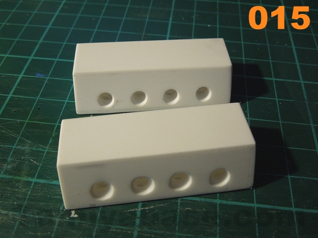
- Once set, remove the bulk of the excess tube with a Dremel fitted with a large sanding drum, then trim & sand back level. "Bell" the inside of the tubes with a Dremel & small spherical burr (see images 014 and 015).
 |
 |
 |
 |
Moving on to the plugs, we're not trying to make perfect 1:12/1:10 replicas of spark plugs - just give the impression of them being there once the model is complete. To that end:
- Cut eight short lengths (3 to 4mm) of 5/32" tube, and eight longer lengths (10-12mm) of .100" rod. Fit one to the other & carefully fit to the 7/32" tubes already in the heads and bond in;
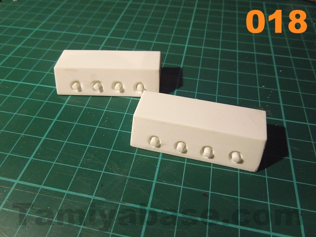
- Once set, trim the rods back to an even 2mm protrudes beyond the side face of each head. This is easier said than done - I trimmed the rods back roughly & sanded off the last couple of mm (see images 016 & 018);
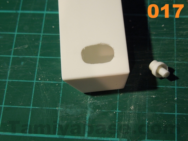
- Note: the fake spark plug assembly is a bit on the delicate side & can escape in to the body of the head ... if that happens, Dremel a hole in the underside & refit/reglue (see image 017).
 |
 |
Spark Plug Caps:
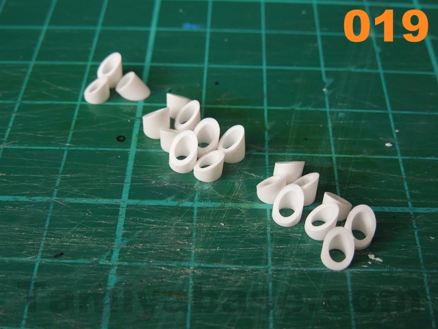
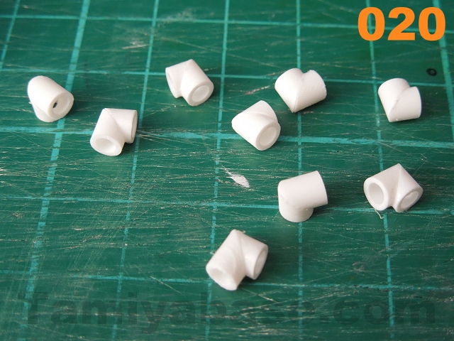
- Cut sixteen pieces of 5/32" tube at 45 degrees (see image 019) (this is much easier with a rubber profile cutter - think Stanley knife blade meets a pair of scissors) with about 1mm on the short side. Fix pairs of these together to make a 90 degree turn (see image 020), fit .100" rod into one end, cut off with 2mm showing & glue in (see image 021);
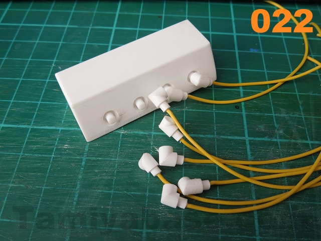
- Use a 1.2mm drill bit to make a hole in the .100" rod in each cap for the HT leads. For the leads themselves, I cut eight 120mm lengths of yellow 7/0.20 instrument wire (see image 022). Don't glue the wires in or the spark plug caps to the heads just yet...
 |
 |
 |
 |
004 Crankcase:
- Cut two ends from 1.5mm sheet - dimensions are 22mm for the top, 27mm for the bottom, 49mm top to bottom, angles at the top are 45 degrees & 23mm long. Vertical bits at the lower end are 18mm high, and the lower angles are whatever they need to be to join up...
Many of the other parts share a dimension, so cut a 47mm wide strip from 1.5mm sheet. From that, cut:
- a 27mm wide piece for the base;
- a 24mm wide piece as bracing (glue to the top side of the base with even gaps down the long edges);
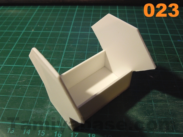
- two 18mm wide pieces for the lower sides - bond these and the base/brace together with the ends (see image 023);
- Cut a 22mm wide piece for the top (sand the long edges to a 45 degree angle);
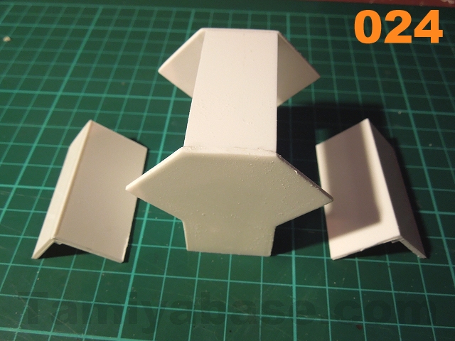
- An 18mm wide brace (glue to the underside of the top panel with even gaps & along the long sides) - bond those pieces in between the end panels (note crankcase in middle of image 024);
- Two 24mm wide pieces (to make up the upper angled sides);
- Two 18mm pieces (for the lower angles).
- Cut two 47mm long bits of 2mm square for bracing;
- Sand a 45 degree angle on the lower edge of the lower panels, then bond the 3 parts together (see outer parts in image 024);
- Fettle as required to fit the crankcase & bond in;
- Fill all joints, then wet sand back (see image 025).
 |
 |

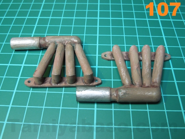
005 Exhausts:
There are lots of options for the exhausts, the simplest would be a set of slightly angled slash cut headers, but I wanted to go a little further & make proper manifolds & stub (open) exhausts. In hindsight I should have made them curved or at least more "lobster backed (cut three pieces with 22.5 degree angles). Feel free to improve on my design, but if you do want to replicate my "simple" version:
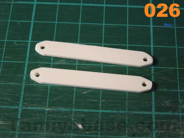
- Cut a 7mm wide strip from 2mm styrene sheet, cut off two 47mm long pieces: these will form the manifold bases;
- Sand the edges & faces square/smooth, then sand the ends to a blunt point. Drill a 2mm hole near the end - try and make all four ends as identical as possible (see image 026);
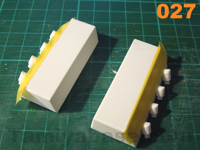
- Temporarily fit the spark plug caps (i.e. without gluing) - a downward & backward angle makes the most sense - and add a strip of masking tape (see image 027);
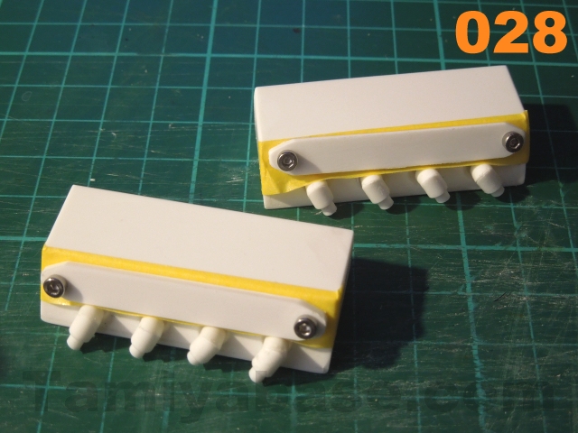
- Use the manifold bases to make drilling points on the heads, drill 1.5mm holes & refit the bases with M2x4 screws (see image 028);
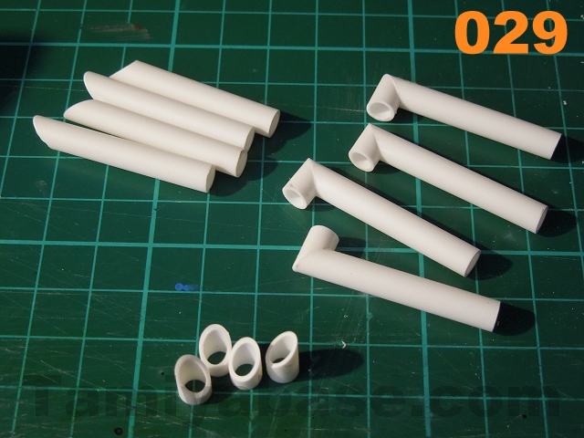
- Cut eight bits of 7/32" tube at 45 degrees (3mm on the short side) and a further eight longer bits (32mm on the short side). Glue each short to a long to make a 90 degree bend (see image 029);
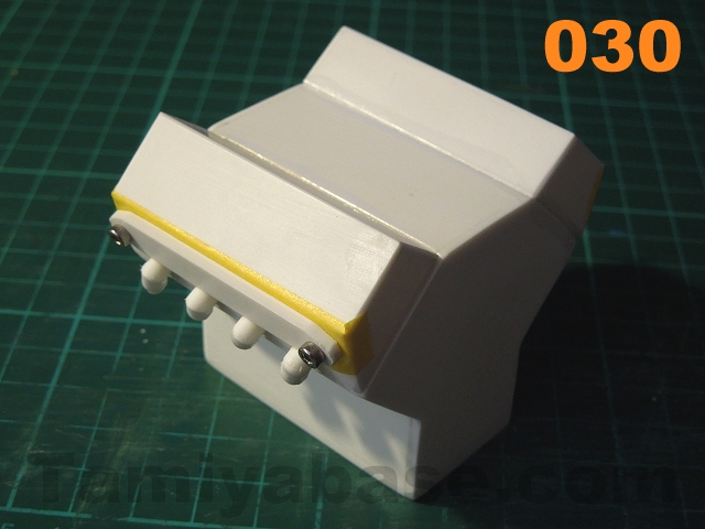
- Glue the heads to the crankcase being very careful not to accidently glue the plug caps on - in fact it's probably worth only gluing the tops (as fitted) and ends of the heads at this point (see image 030);
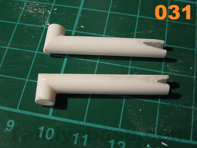
- Pick two of the downpipe assemblies to fit to the middle two positions on one side, and sand or Dremel off a little from the lower left side of one & the lower right of the other so they can be fitted with the correct gap at the top & touching at the bottom (see images 031 & 032);
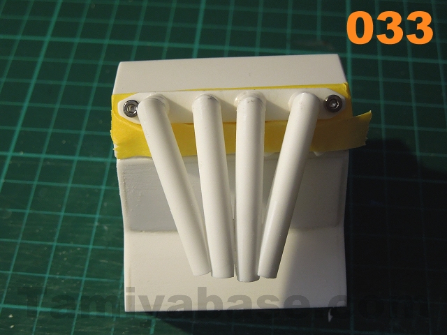
- Take a bit more off the same places on another two & fit to the outer positions (see image 033);
- Even up the length of the 4 pipes, then cut off two 18mm lengths of 9/32"(7.1mm) tube & shape to fit (see image 034);
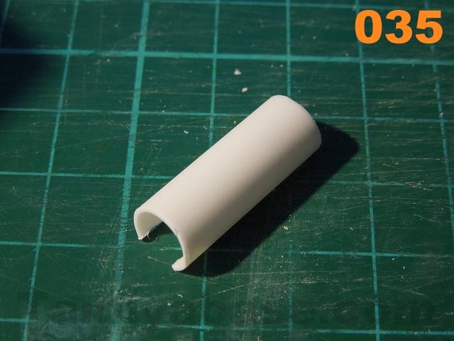
- Cut off a 25mm length of 11/32" (8.7mm) tube, angle one end & cut a slot in the top to fit over the ends of the downpipes (see image 035);
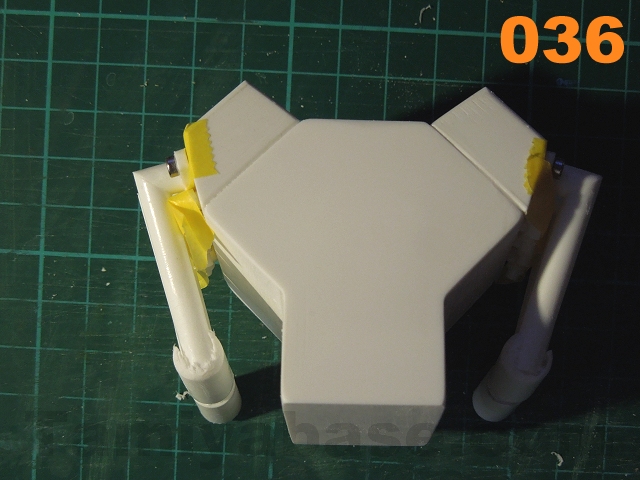
- Cut another (20mm) length to fit on the end of the 9/32" pipe fitted earlier. Dremel/sand the forward ends to shape (see image 036);
- Repeat for the other side (a mirror image);
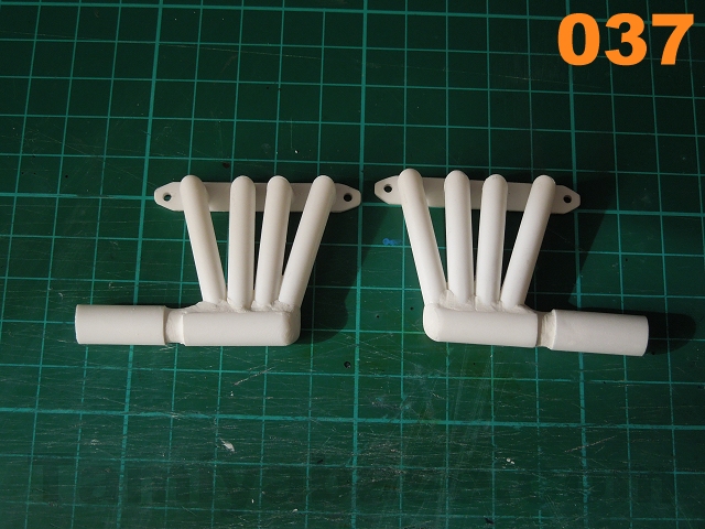
- Fill/smooth any gaps with filler or epoxy putty (e.g. Milliput White) (see image 037).
 |
 |
 |
 |
 |
 |
 |
 |
 |
 |
 |
 |
006 Sump:
- Cut a 48mm x 25mm rectangular piece from 0.75mm sheet and round the corners slightly;
- Cut a 44mm x 21mm piece from 1.5mm sheet, round the corners & edges on one face. Bond to the previous piece with an even gap around the edges, weighting it down to stop warping while the adhesive cures;
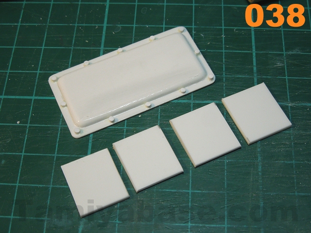
- Cut twelve 1mm lengths from a 1/16" (1.6mm) round rod & bond on around the perimeter as fake bolt heads. These are very fiddly: and getting square, even length cuts is difficult - I cut off a lot more & picked the "best" ones. I'd also suggest using regular Poly glue to stick them on as the longer setting time is helpful (see image 038);
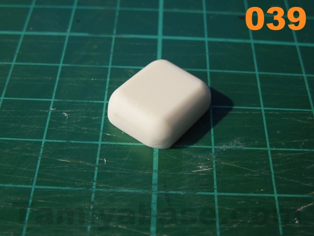
- Cut a 15mm wide strip from 1.5mm sheet, then cut off four 17mm long pieces. Bond these together & fill any gaps;
- Wet sand to a rectangular shape, then radius the 4 corners and bottom face (image 039);
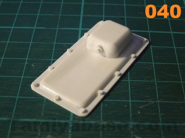
- Add a drain plug detail (e.g. slivers of 1/8" & 1/16" rod) & bond the two main parts together (image 040). Don't glue the sump to the block just yet - leaving it separate will make painting easier.
 |
 |
007 Distributor:
Having decided to fit spark plug leads & so on, they need to terminate in a distributor. Due to wanting to keep the distributor a plausible size, it won't be possible to create "rubber" fittings this end of the same dimensions as the spark plug caps, we'll have to cheat a little in the name of simplicity:
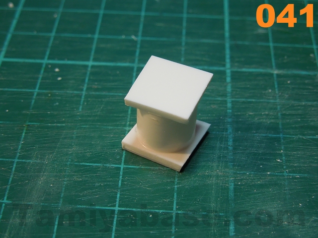
- Use a short length of 10mm wide masking tape to mark off a portion of 7/16" (11.1mm) tube. Cut off with a razor saw & sand the cut end(s) smooth;
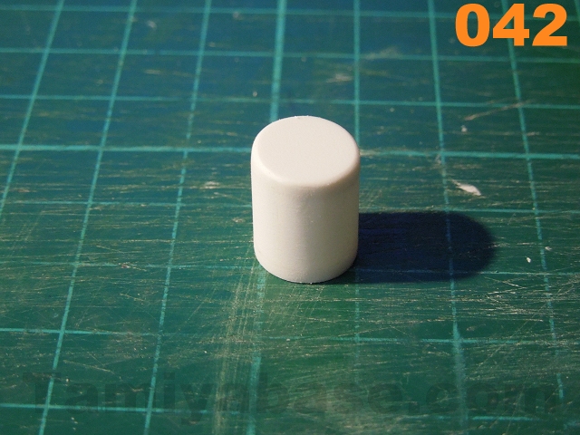
- Cut two 12mm squares from 2mm sheet, bond to each end of the tube above (see image 041), and Dremel/sand back to round once set (image 042);
- In one end, drill a 3.2mm hole & fit a 25mm length of 1/8" (3.2mm) round tube or rod. While you've got the drill out, drill a hole 3.2mm diameter hole 4mm in from each edge of the right rear corner of the engine block (as it would be if you were sitting in the drivers' seat) a few degrees leaning out from the vertical. Don't glue the distributor in yet;
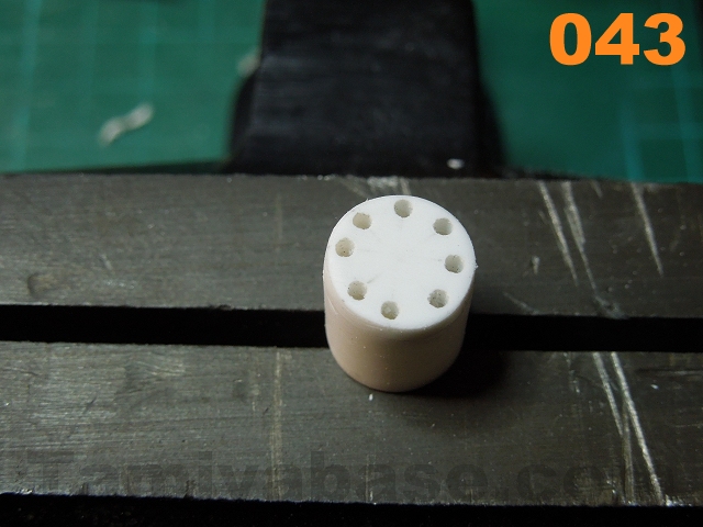
- On the other end of the distributor, mark out and drill eight equally spaced 1.1mm holes (image 043);
- Cut a 1mm strip from 1mm sheet & use that to fake the lower edge of the distributor cap, about 1/3rd of the way down from the top;
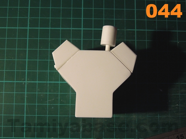
- Temporarily fit the distributor (image 044), but again - don't glue it in yet, it just needs to be there to check clearance as the inlet manifold, carburettor and air filter are made & test fitted.
 |
 |
 |
 |
Note: an obvious way of increasing the detail level here would be to add a ninth, central lead and a coil.
008 Inlet Manifold & Carburettor:
Note: this is an area ripe for greater detailing ( but I did call this a "simple" build & something has to give) ... A larger bore/more detailed/curved manifold and various details on the exterior of the carburettor, such throttle & choke levers & cables come to mind...
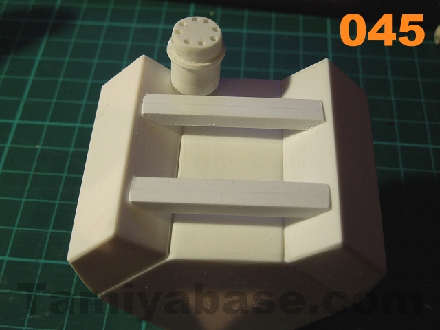
- Cut four pieces of 3.2mm square strip to a length & angle suitable to sit between the heads - mine were 38mm long & angled at 40 degrees (see image 045);
- Glue in pairs (but don't glue to the heads until after painting);
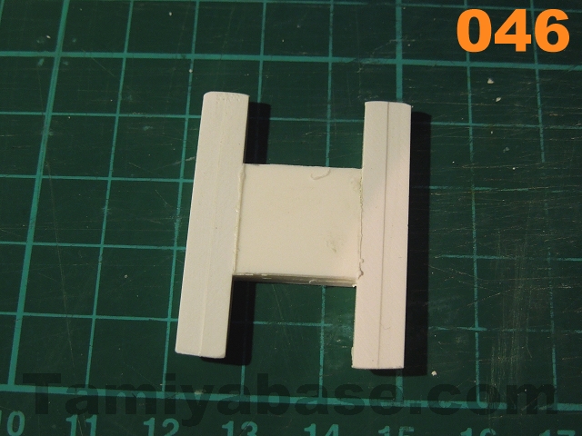
- Cut two 16mm square pieces from 1.5mm sheet. Glue them together, then to the paired square rods to form an H shape (see image 046);
- Cut two 14mm x 19mm pieces from 0.5mm sheet, round corners slightly & glue to the H - one each side (see image 048);
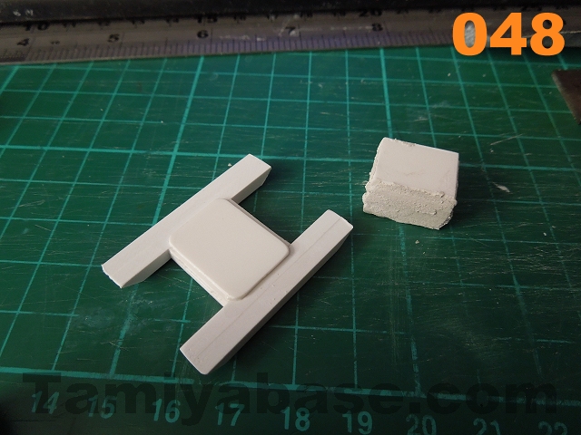
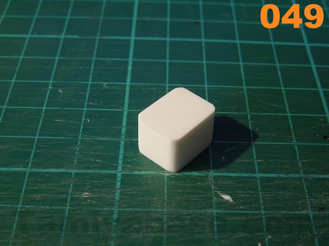
- Cut five 12mm x 15mm pieces from 2mm sheet (see image 047), stack together, glue, fill (see image 048);
- Wet sand & radius the 4 corners before gluing to the inlet manifold (see image 049);
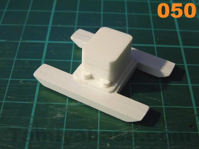
- Cut two thin pieces of 1/8" rod. Cut those in halves & glue between the manifold & carburettor (see image 050).
 |
 |
 |
 |
 |
 |
009 Air Filter/Cleaner:
There are a couple of options for an old school looking air filter - either a stout, closed, round unit with a long "spout" directed at a cool area under the bonnet (hood), or a slightly bigger round unit, possibly with visible filtration around the middle. I've gone for the latter, made up from a number of layers. Ideally you'd cut these out with compass cutters, but mine don't go below 40mm so I used a Tamiya 10ml glass jar to mark out two each of 34 mm and 30mm discs* on 2mm styrene sheet, then cut them out with a combination of craft knife, Dremel (large drum) and sanding (see image 051).
* Note: I later remembered I'd bought a circle template for just this sort of eventuality ...
Using improvised templates meant I needed to find the centres before I could move on: I used a small centre square, but the tool free way of doing it is to draw a chord (straight line) across your round thing, measure the line, draw a line at 90 degrees halfway along it, repeat with another chord, and where the two 90 degree lines intersect is the centre.+
The centre square (being a 90 degree square with another piece at 45 degrees to the two - (see image 051)) just takes a couple of steps out - draw two lines & where they cross is the centre.
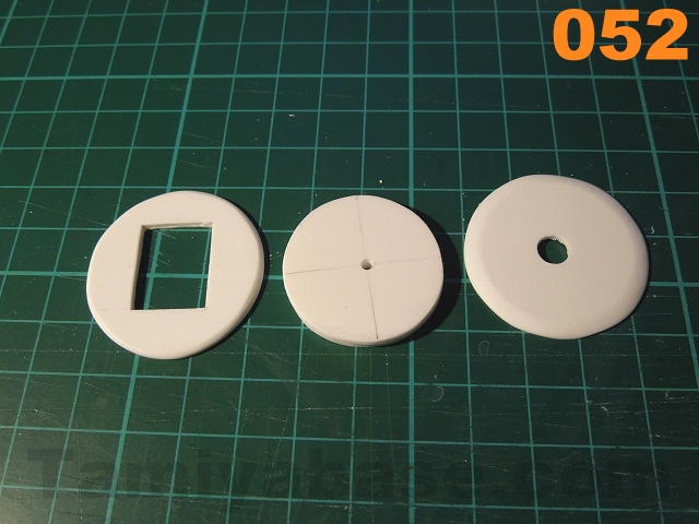
Looking at the layers individually, starting from the bottom (and left to right in image 052):
- A single 34mm OD disc of 2mm styrene sheet with a 14mm x 18mm rectangular cutout in the centre. The lower outside edge should be tapered slightly;
Two 30mm OD discs (again from 2mm sheet), 2mm hole through the middle;
Another 34mm OD disc (2mm sheet) with 6mm hole in centre. The top outside edge should be tapered slightly.
To build the cleaner:
- Bond the four layers together;
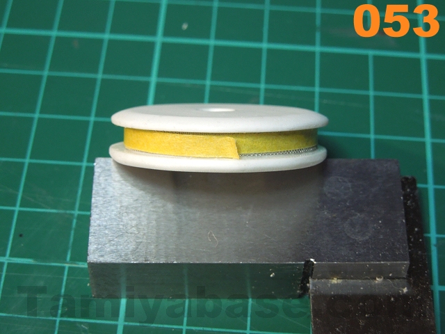
- Cut a 3.5mm wide, 95mm long strip of fine metal mesh, and carefully pre-form to a circular shape.
- Mix up a small amount of 2-part epoxy adhesive (e.g. Araldite) & apply to the recess around the middle of the cleaner. Fit the mesh & allow to set - some masking tape around the mesh will probably be required (see image 053);
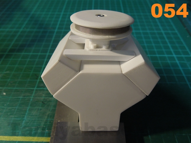
- Allow to set overnight. Drill a 1.5mm hole top centre in the carburettor - and fix together with an M2 x 10mm screw. Sit the assembly on top of the crankcase to admire your handiwork (image 054) - but don't glue it on yet.
 |
 |
 |
 |
010 Timing Chain Case/Waterpump Housing:
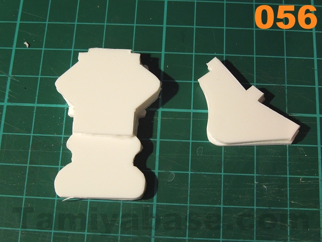
Again, this is very much simpler than the real thing. I can't give you dimensions for these parts as I drew them freehand - just use the bits on the plan as a guide to make a convincing shape:
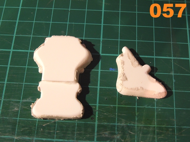
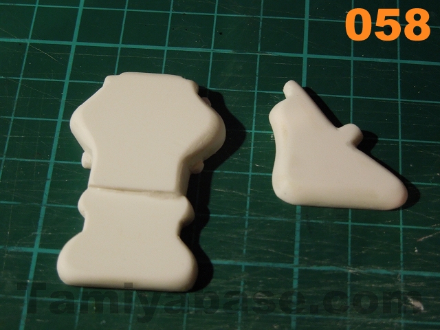
- Cut out one each of the first three parts from 2mm sheet (see image 055) & glue together (image 056), sand/fill (image 057) and radius the outside edges on the front face (image 058);
- Cut out two of the second shape (again from 2mm sheet) , glue together & heavily radius the edges on the front face;
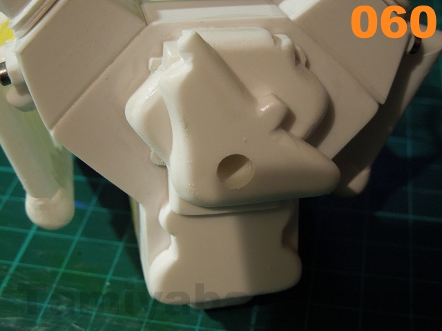
- Glue the two sections to the crankcase front (image 059), then drill a 0.8mm hole for the fan spigot, working up in steps to 5.5 mm (image 060);
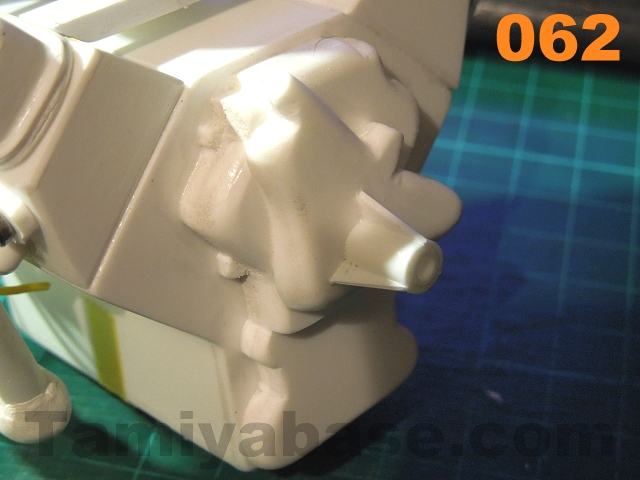
- Glue in a length 7/32" tube, then cut back so 9mm is protruding; Cut a short length of 5/32" tube, fit so the ends match & glue in;
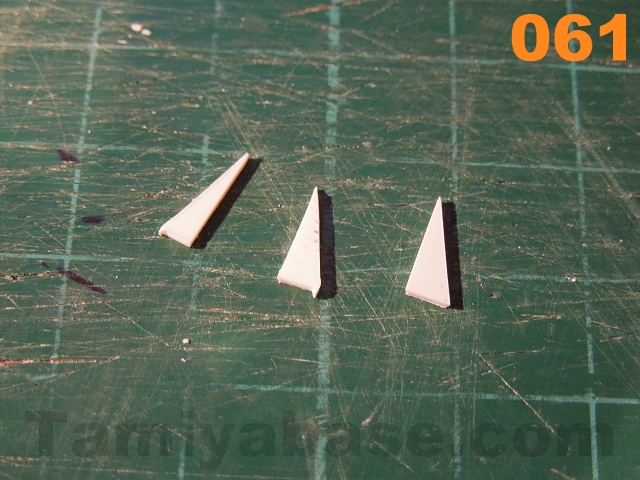
- Cut three triangular bits from 0.75mm sheet, 90 degrees & 9mm on the long side, 3mm on the short (image 061). Glue these spaced at 120 degrees around the tubes (image 062).
 |
 |
 |
 |
 |
 |
 |
 |
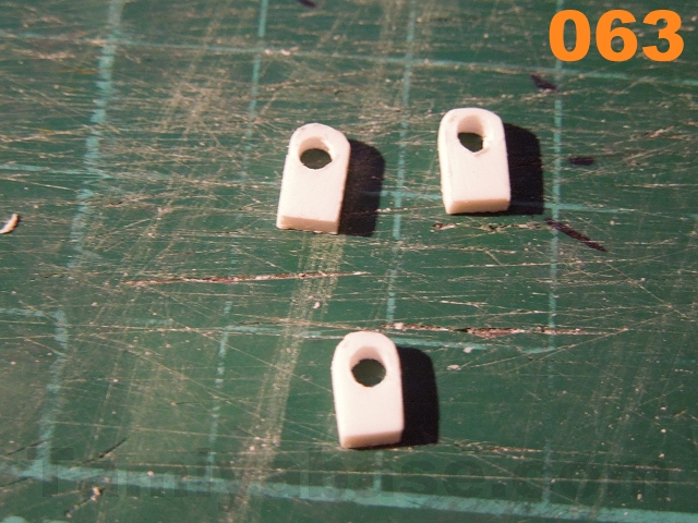
011 Lift Points:
If you're going to be using the engine in a diorama (especially if you want it to dangle off on an engine hoist) rather than fitted in an engine bay then you'll need some lift points - I cut very simple rectangular tabs from scrap 2mm styrene sheet, drilled a hole one end & rounded that end before gluing on - two at the front & one at the rear.
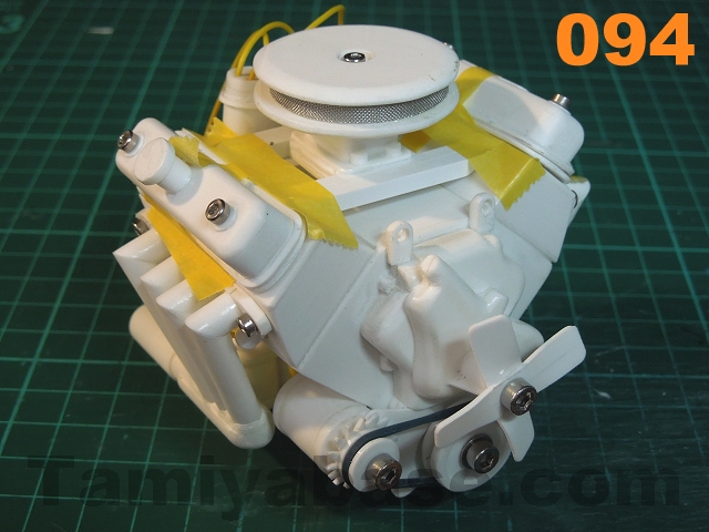
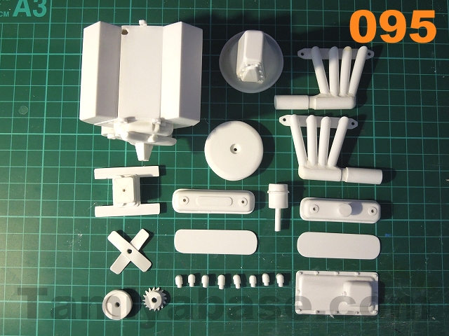
Note: actual dimensions were 4mm x 6.5mm with a 2.5 mm hole. I forgot to take a specific picture of the locations during the build, but later pictures (for example images 094 and 095) show the clearly enough.
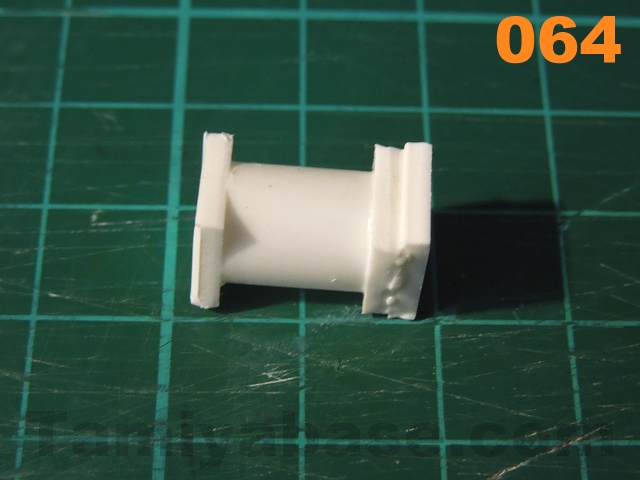
012 Oil Filter:
My research seemed to indicate there were two possible orientations / locations for the oil filter - a horizontal canister screwed directly to the left side of the crankcase 2/3rds of the way back - or one vertically on the right side ... I'd compromised myself with the position of the exhaust manifolds, so went for the latter:
- Start with a 10mm long piece of 11/32" (8.7mm) tube with one bit of 2mm sheet on one end & two on the other (see image 064);
- Completely round the end with one layer on, the double layered end needs to keep a flat side to fit to the crankcase (i.e. make a "D" shape);
- Lightly file eight flats near the bottom of the cylinder to simulate the shape of the 1:1 item (where strap or chain wrenches can be used to remove it) (see image 065);
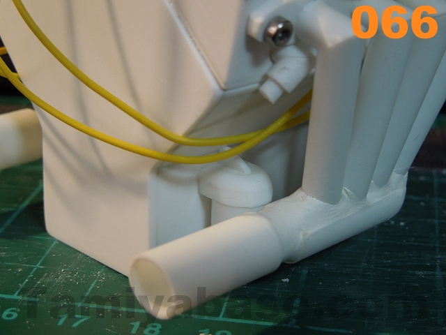
- Glue to the crankcase, adding a triangular fillet to the top as bracing (see image 066).
 |
 |
 |
Fuel Pump/Filter:
I omitted this entirely, but a simple way of replicating one would be to make a longer/thinner version of the oil filter above & fix to the front left corner of the crankcase.
013 Crank Pulley:
Even the most modernised Y-block engines still have something here - even if it's just a simple pressed dome marked with graduations to help with engine timing, so I don't think this should be skimped on entirely, whatever setup you're imagining. I needed an old school pulley to "drive" the alternator though:
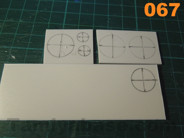
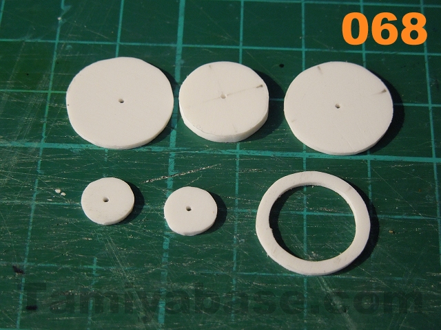
- Start by marking out three 17mm diameter circles and two 8mm OD on 1mm sheet, and one 14mm diameter on 2mm sheet. If your template has marks at 90 degrees around the circles it's worth marking these too so you can find the centres easily later (see image 067);
- Cut/Dremel/sand round. On one of the 17mm OD 1mm layers, remove the middle so just a small band is left (see image 068);
- Glue one of the 8mm pieces to the crankcase & once set (see image 069), drill a 2.5mm hole through the centre & the chain case behind it;
- Glue the remaining layers together(see image 069) & once set, drill a 3mm hole through the centres;
- Fix the pulley to the crankcase with a short M3 cap head screw, just loose enough to turn by hand.
 |
 |

014 Alternator:
This is something else that could be omitted, or gussied up some more if the muse takes you ... Again, I went for a simple version, the pulley is very much like the section above, only smaller:
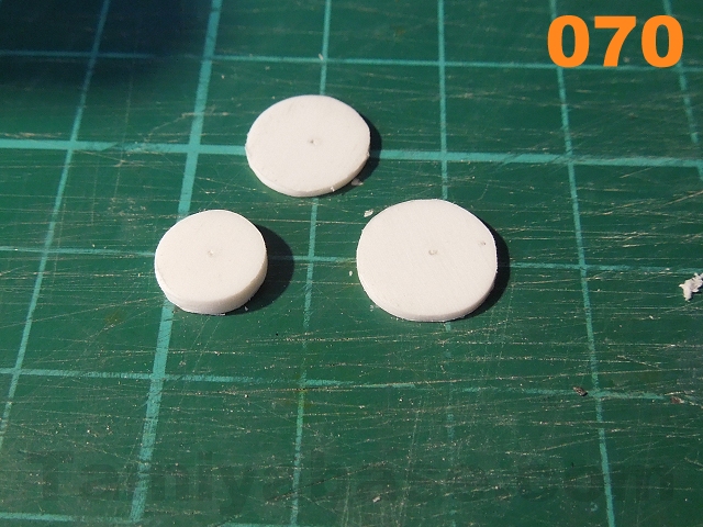
- Cut out two 10mm diameter circles on 1mm sheet, and one 8mm diameter on 2mm sheet (see image 070);
- Glue those 3 bits together & drill a 3mm hole through the middle (see image 071);
- Cut a 14mm OD piece from 1mm sheet, mark a 10mm circle on it & 16 points around the perimeter (22.5 degrees) (see image 072) & cut notches to represent the fan blades (see image 073);
- Glue that to the pulley (see image 074) & drill a 3mm hole through the fan centre.
- The alternator body is a 12mm long bit of 1/2" (12.7mm) tube with 2mm thick end pieces (see image 075) - round them off & drill holes in the centre of one end, working up in steps to 5.5 mm;
- Glue in a length 7/32" tube, then cut back so 2mm is protruding; Cut a short length of 5/32" tube, fit so the ends match & glue in;
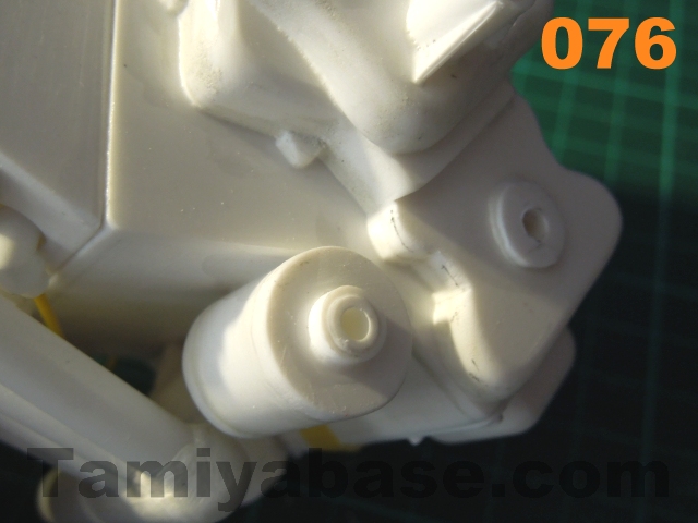
- Remove the crank pulley from the crankcase (if you haven't removed it already), then glue the alternator body in the angle of the crankcase on the right side so the end of the small tubes lines up (see image 076);
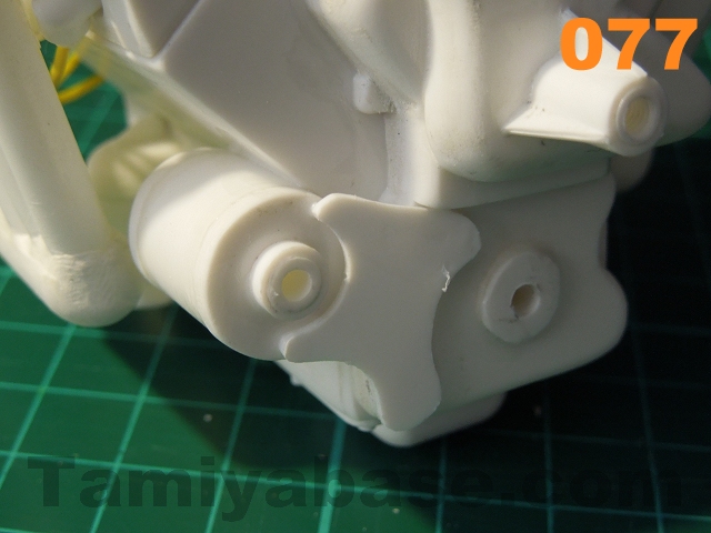
- Cut & glue on a bracket from 1mm sheet (see image 077) - shape it as you like but remember the 1:1 car part would probably made from cast alloy or pressed steel so wouldn't be particularly chunky;
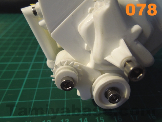
- Refit the pulley, plus the smaller one on the alternator with another 10mm M3 screw (see image 078);
- Find & fit a suitable elastic band to stand in for a drive belt.
 |
 |
 |
 |
 |
 |
 |
 |
015 Fan:
Most modern 1:1 applications would have a thermostatically controlled electric fan fitted directly to the radiator, but I liked the idea of an old fashioned fan ... The construction may look ridiculously basic, but it is a genuine 1950's (and earlier) design & can be run in two configurations - two of the flat, twisted bits of steel where you need that much cooling, or just one in colder climates.
My setup is two 7mm wide, 30mm long strips of 0.75mm sheet with a 3mm hole in the centre, each gripped in flat bladed pliers & the ends twisted round (see image 079) before gluing together & fitting on the waterpump housing with an M3 x 10mm screw.

Engine Mounts:
These depend very much on the vehicle the engine is to be fitted in, so I haven't made them a part of this build - but a typical front mount seems to be a pressing, basically L-shaped in form, with the vertical part behind the crank pulley, and the horizontal part underneath the pulley (which then bolts to a cross member. A typical rear setup is two triangular brackets (sometime "feet" as part of the casting) on the bell housing, which bolt to another crossmember via rubber isolating blocks.
Radiator:
As I haven't included the points where coolant hoses would attach to the engine, I felt I could leave the radiator out too - especially as the dimensions will depend so much on the size and layout of whatever vehicle you're fitting the engine to.
If you've got this far, a radiator shouldn't be too much of a challenge anyway. ;)
016 Bell Housing/Gearbox:
This is another area with a great deal of options - if you wanted to show an engine being worked on, you could leave the back end of the engine very open (a simple disk of styrene plus a detail ridge just inside the edge - to show where the rest has been removed), or a very detailed gearbox (including ridges & bolts, dangling UJ, gear lever etc) ... Again, I'm going for a "simple" version:
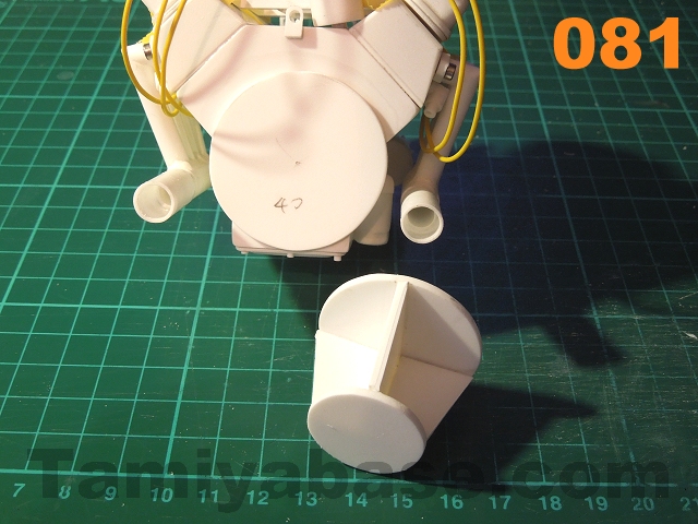
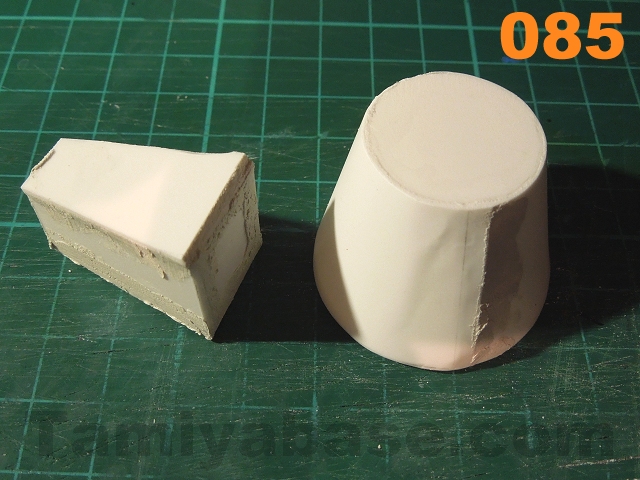
- Cut 40mm, 36mm and 25mm discs from 2mm sheet (see image 080);
- Cut a 20mm wide strip from 2mm sheet & cut to form spacers/bracing between the two ends of the bell housing: one needs to be 36 mm on one side and 25mm on the other, two need to be 16mm on the long side and 10mm on the short (see image 080 & 081);
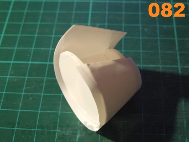
- Skin the bell structure in 0.25mm sheet - the shape in the plans should be seen just as a guide- cut one end as shown but the rest should be cut oversize & trimmed back once glued on (see image 082);
- Put a second layer on to iron out any flaws & stiffen the structure up.
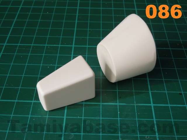
- Moving on to the gearbox section, a number of parts 1.5mm thick are needed (see image 083):
- Base & top are 30mm long, 18mm at one end, tapering to 10mm;
- Sides are 30mm long, 20mm tall at one end, 14mm at the other;
- Large end: 20mm high x 15mm wide;
- Small end: 15mm tall x 7mm wide;
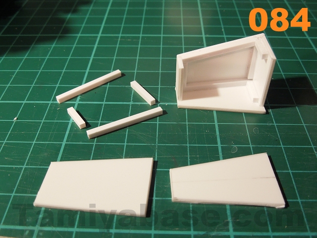
- Glue all those together (see image 084), using 2mm square beam for internal bracing (each side is two 27mm pieces, plus one each of 10mm & 6mm long; large end is two 11mm lengths);
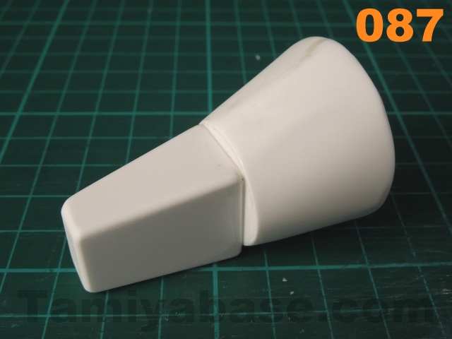
- Fill (see image 085) & sand any flaws (see image 086) also putting a small radius on the edges of the gearbox, then glue the gearbox to the bell housing - both parts should be flat on the bench when you glue them together, even though they look mismatched like that at present (see image 087).
- Mix up a small amount of epoxy putty & use that to form fillets around the mismatched ends ((see image 088) including the underside (see image 089). I'd recommend Milliput in particular as it can be wetted & smoothed out before it sets - that can save a lot of sanding time later. Some irregularities are inevitable though, so sand smooth once set;
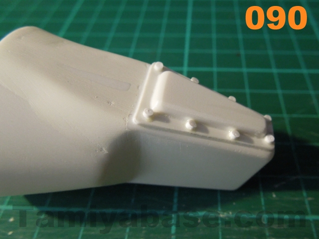
- Make a small sump panel to go on the bottom of the gearbox:
- Base is cut from 0.75mm sheet - 28mm long, 16mm at one end, tapering to 8mm at the other; round the corners;
- Relief detail panel (bowl) is cut from 2mm sheet - 23mm long, 11mm at one end, tapering to 5mm, round the corners & radius the edges on one face; glue centrally to the base;
- Cut eight slices of 1/16" round rod & space evenly along both edges;
- Glue to underside of gearbox (see image 090);
- Cut a 1mm wide strip from 1mm sheet (tip: doing it slowly & with multiple light cuts means it'll curl less), trim down to approx 120mm, bend around something small & round, then glue to the wide end of the bell a bit at a time, cutting it down to the final length (see image 091).
Don't glue the gearbox on to the crankcase just yet...
 |
 |
 |
 |
 |
 |
 |
 |
 |
 |
 |
 |
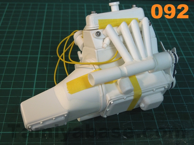
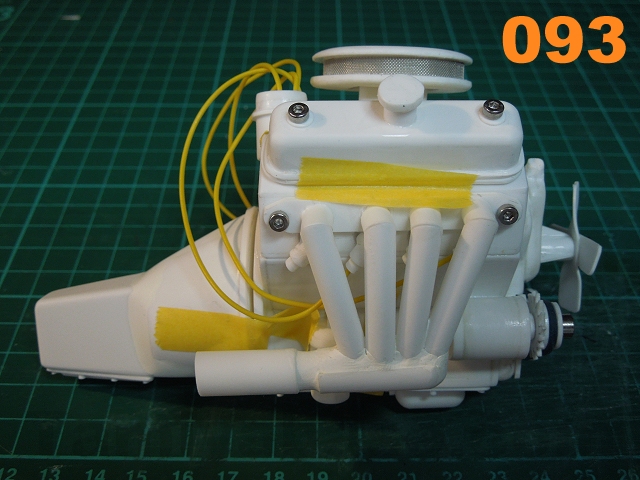
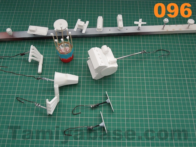
Well that's it built - with the various sub assemblies held on with glue, screws, tape or gravity (as appropriate), it should look something like images 92, 93 & 94.
 |
 |
Painting
Disassemble as much as possible before painting, e.g. untape temporary fixes & remove screws (including the purely decorative ones).
Fix parts to something for spraying - for medium sized parts I have a "spraying stick" - a 18"-ish length of wood with a number of holes, plus several M3 (ish) machine screws fixed through. Parts can then be held on through existing holes (pulleys & fan in this case - with a bit of Blu Tack), or holes added where they won't show (underside of inlet manifold, sump, air filter, valve covers).
Larger bits (crankcase, gearbox) also get an extra hole drilled & are fixed on to long M3 (ish) fasteners with a bit of stiff wire wrapped round & formed into a hook. Exhaust manifolds got the same treatment (due to not having rooming on my spraying stick) as did the valve cover gaskets (just with a lump of Blu Tack instead of a hole).
Spray with a suitable plastic primer (I used Hycote White Plastic Primer).
 |
 |
Paint according to taste - this could be anywhere between shiny & new, to really rusty - but bear in mind the materials the 1:1 engine would be made of, for instance:
- Gearbox body, inlet manifold, waterpump housing, alternator brackets - cast alloy so won't rust (though they will oxidise to a translucent white fur that can be replicated with flat base);
- Crankcase, sump, fan, pulleys, crankcase sump, valve covers, distributor bottom half, exhausts - cast iron or mild steel so will rust;
- Air cleaner: usually chrome plated steel, so will rust (eventually);
- Distributor top & spark plug caps: Bakelite type plastic, so won't rust.
As I mentioned in the preamble, the paints mentioned here are just suggestions - feel free to work out your own alternatives and/or simplifications. I think you could make a decent go of it with one silver rattle can to spray the whole thing & one jar of medium brown brush paint (for the spark plug caps, dry brushing rust & a couple of washes of different dilution rates), for example.
I'm aiming for a finish that makes it look as though the engine has been in use for a few years - but well cared for in that time. I'll use a number of colours & attempt to weather them back.
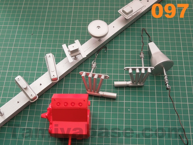
Many of the photos of 1:1 engines I looked at in my research had the crankcase in a bold red. That's a colour that never seems to cover that well when I brush it, so I started by spraying the crankcase with a VW Mars Red aerosol.
As there are a number of parts that can start out as a silvery colour (gearbox, exhausts, valve covers, inlet manifold, air cleaner and sump) I'd suggest it's worth using a rattle can on them too - I used Hycote "Aluminium Coat" but anything silvery will do.
I've already covered dry brushing and washes in a previous instalment so I won't go over the techniques again, just detail the colours I used:
<td'>
Fan
|
Item/Area |
Base Colour |
Weathering/Details |
Image Ref # |
|
Fan |
XF-3 Flat Yellow |
Dry brush with XF-16 Flat Aluminum & Rust*. |
098 |
|
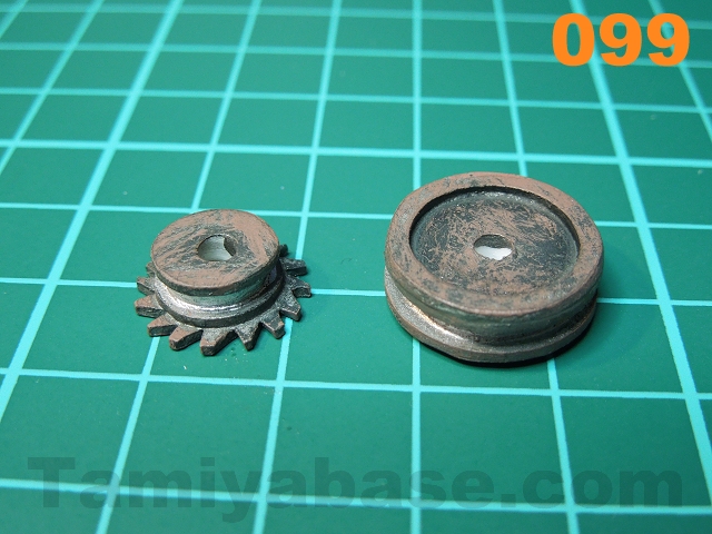
Pulleys |
XF-56 Metallic Grey |
X-11 Chrome Silver on belt seat; dry brush XF-69 NATO Black & Rust. |
099 |
|
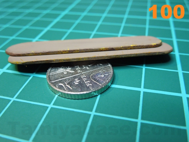
Gaskets |
XF-52 Flat Earth |
Lightly stipple edges with matt orange (50/50 mix X-6 Orange & X-21 Flat Base), XF-3 Flat Yellow & XF-9 Hull Red. Note: this sounds fussy & may even look pointless once you've done it, but trust me - it adds greatly to the believability of the engine as a whole once it's assembled. |
100 |
|
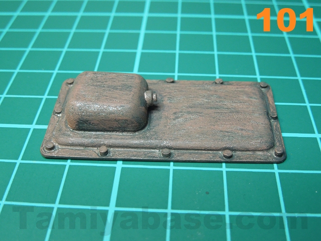
Crankcase Sump |
Aluminium spray |
Dry brush XF-69 NATO Black & Rust*, wash with XF-69 NATO Black to highlight the fake bolt heads. |
101 |
|
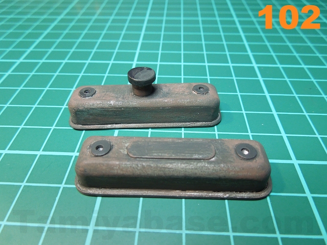
Valve Covers |
Aluminium spray |
Dry brush XF-69 NATO Black & Rust, wash with XF-69 NATO Black. Filler cap & bolt bases: XF-85 Rubber Black. |
102 |
|
Inlet Manifold |
Aluminium spray |
Paint carburettor X-31 Titanium Gold**, wash with XF-69 NATO Black. |
103 |
|
Air Cleaner |
Aluminium spray |
Dry brush/stipple X-11 Chrome Silver & Rust heavy wash of XF-69 NATO Black on the mesh detail. |
104 |
|
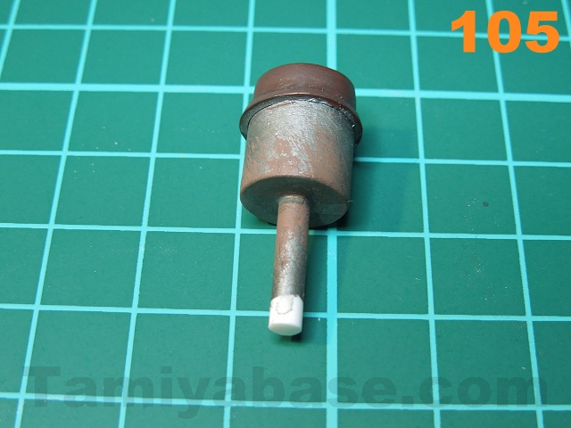
Distributor |
XF-56 Metallic Greyon lower part; Cap ; XF-9 Hull Red |
Dry brush Rust on lower; wash of XF-69 NATO Black all over. |
105 |
|
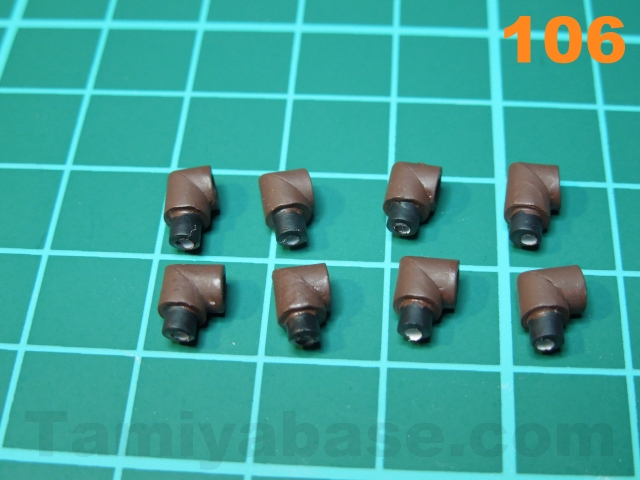
Spark Plug Caps |
XF-9 Hull Red, pick out smaller ends in XF-85 Rubber Black |
(none) |
106 |
|
Exhausts |
Aluminium spray |
Dry Brush XF-56 Metallic Grey, XF-9 Hull Red,XF-52 Flat Earth, and Rust*. |
107 |
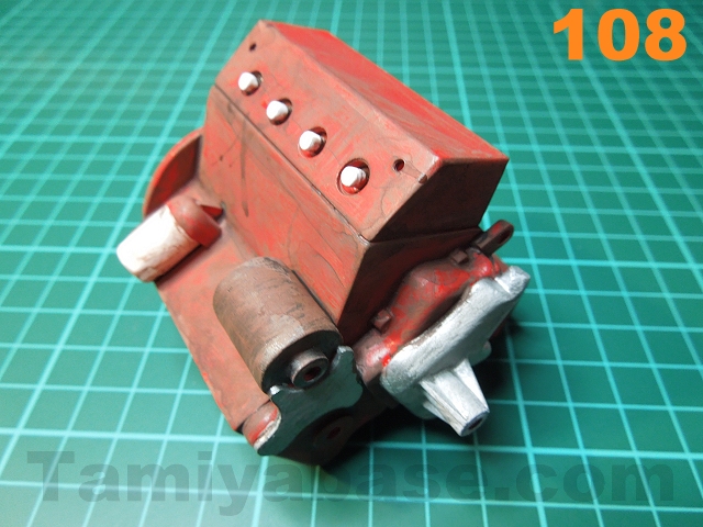
| Crankcase + glued on bits |
Red spray all over. Pick out details, e.g. + visible ends of spark plugs & oil filter in XF-2 Flat White, water pump housing & alternator bracket in XF-16 Flat Aluminum, alternator ends with XF-56 Metallic Grey, alternator body with XF-69 NATO Black. |
|
108 |
|
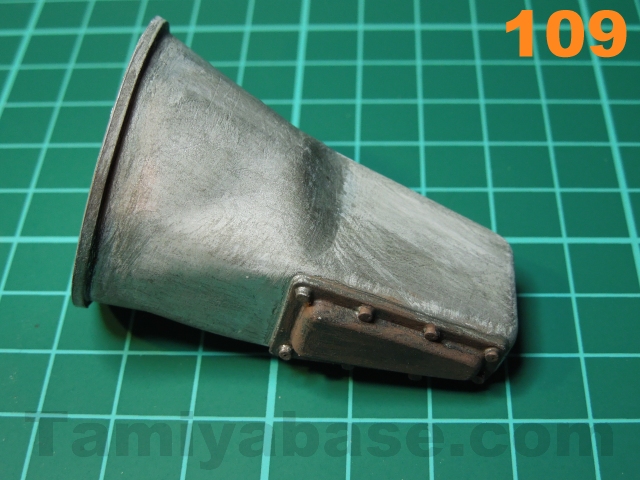
Gearbox |
Paint body with aluminium spray, paint sump XF-56 Metallic Grey |
Lightly dry brush with XF-56 Metallic Grey X-21 Flat Base. |
109 |
* Note on "Rust": use Humbrol #113 Rust (or mix Tamiya XF-23 Light Blue & XF-9 Hull Red)
** An alternative to "Titanium Gold" is to mix X-26 Clear Orange & XF-16 Flat Aluminum.
 |
 |
 |
 |
 |
 |
 |
 |
 |
 |
 |
 |
Assembly
There are a few areas that need to be done in sequence (plug caps before exhaust manifolds for example), this is the order I reassembled the engine in & I didn't have any problems:
- Refit the M3 screws to the crankshaft pulley, alternator pulley & fan, put a tiny dab of superglue on the end of the threads, and refit to the crankcase so the parts are free to rotate;
- Refit the M2 screws to the valve covers, glue the gaskets to the covers, and to the heads, making sure the one with the filler cap goes on the right side;
- Put a dab of superglue (Cyanoacrylate - or CA) on one end of the plug HT wires & fit to the plug caps;
- Glue the sump to the body of the crankcase with superglue;
- Glue the distributor to the crankcase - the top should lean slightly to the right;
- Screw the air cleaner to the carburettor/inlet manifold, apply CA to the inlet stubs & glue to the top of the crankcase;
- Glue the plug caps to the fake spark plug ends, angle backwards at approx. 45 degrees;
- Screw the exhaust manifolds back in place;
- Cut eight 2mm lengths of black heatshrink tubing & fit one over each of the HT leads;
- Glue in the HT leads according to the diagram (image 110) - some leads may need trimming. Slide the heatshrink tube to the distributor end of the wires & carefully shrink on with a hot air gun. Paint over any gaps with XT-85 Rubber Black;
- Glue the gearbox to the back of the crankcase (I used Blu Tack as a temporary fix as I'll be modifying the engine before fitting.

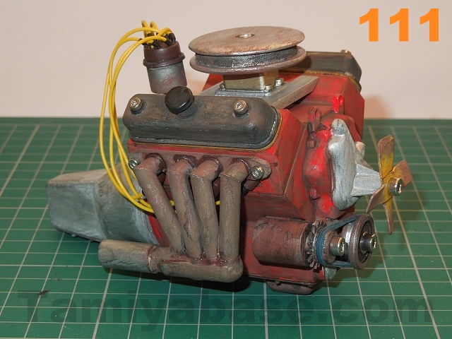
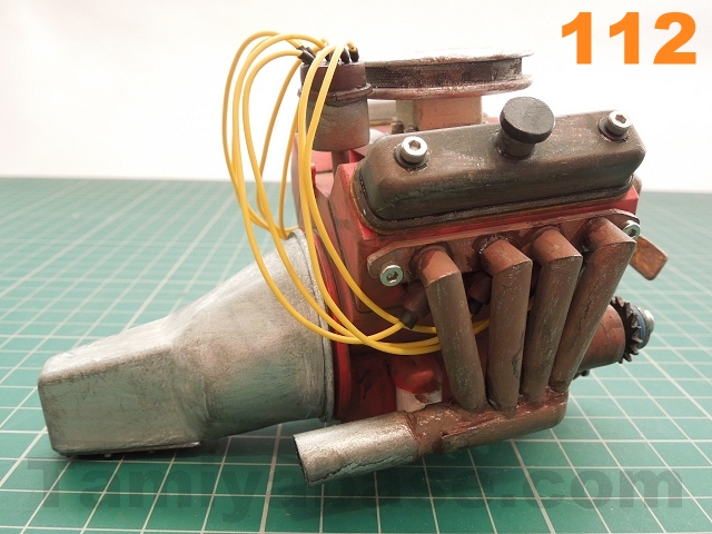
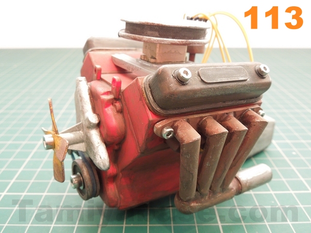
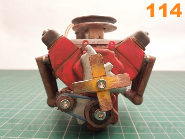
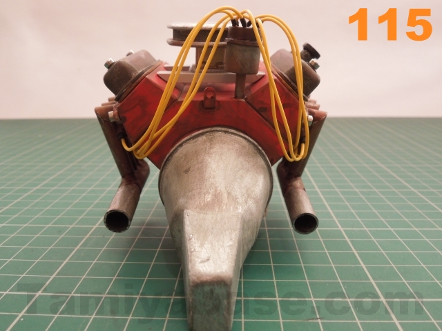
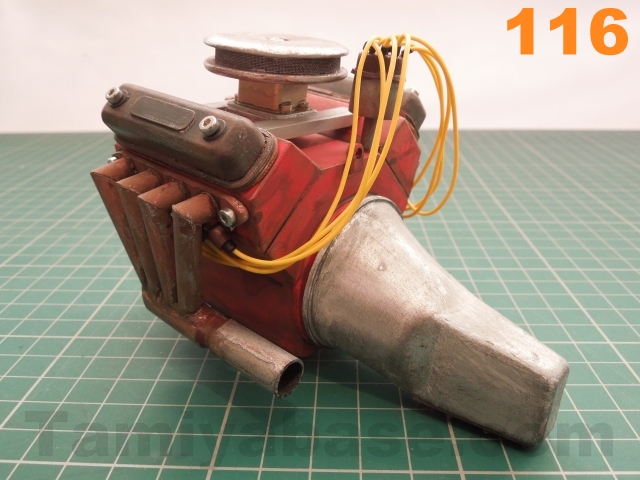
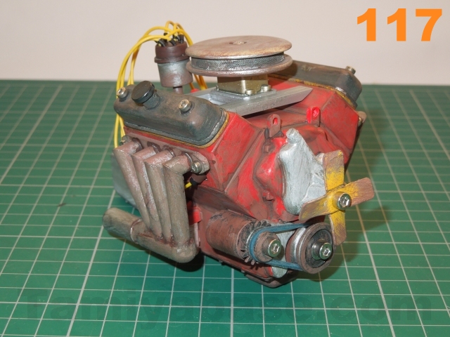
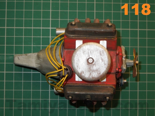
Some photos of the finished engine:
 |
 |
 |
 |
 |
 |
 |
 |
 |
Afterword
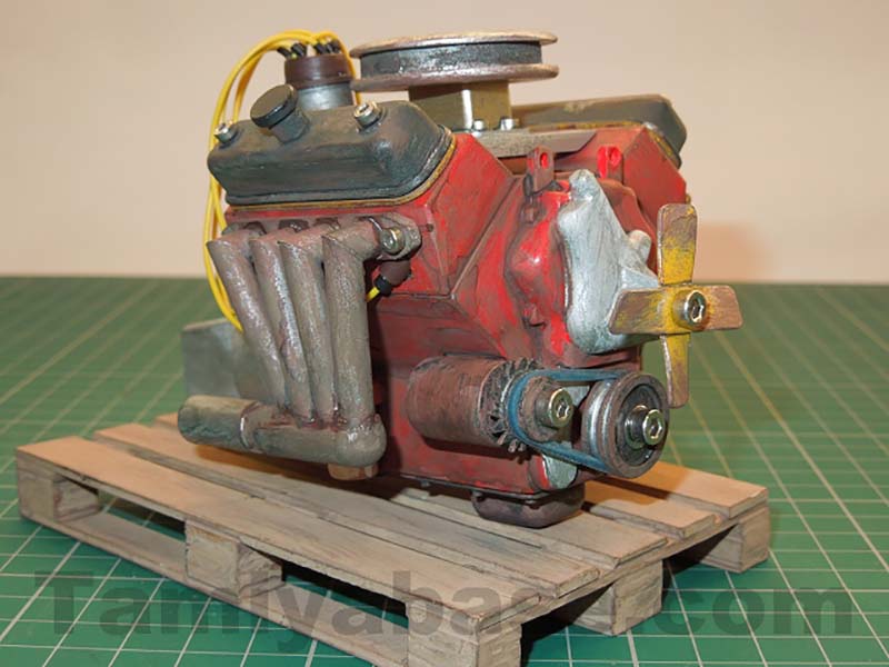
Well, that's it built. It's up to you what you do with it - stick it on a scale pallet, design & build your own engine hoist to dangle it from, or install it in an RC truck.
Even if you don't want to build one, I hope at least this & the preceding articles have been an interesting read and have provided an answer to "how do you do it?".
My plans are that there will be a follow up to this - an "advanced" level guide on taking an off road truck body from the idea stage, through to making plans, card prototypes & building a detailed scale, RC model.
Download plans:
Right click and "Save target" / "Save link" or similar.
________________________
Written by TB member Jonny Retro