

Introduction: The "Other" Willys
Important note: no vintage Willy parts were irreparably damaged or modified in the making of this car.
Several anomalous variations of the Wild Willy appear in Tamiya publications, press releases, manuals, and on boxes: these vary from trivial differences to wild variations but are “official” in my view.
Two appear alongside the “box art” form seen in the 1982 Tamiya promo video – one is standard apart from having rear arm stays without holes, the other appears to be standard apart from having a silver driver helmet.
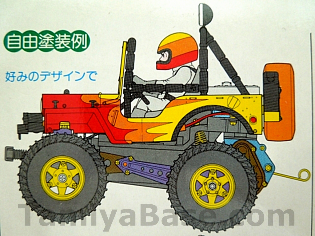
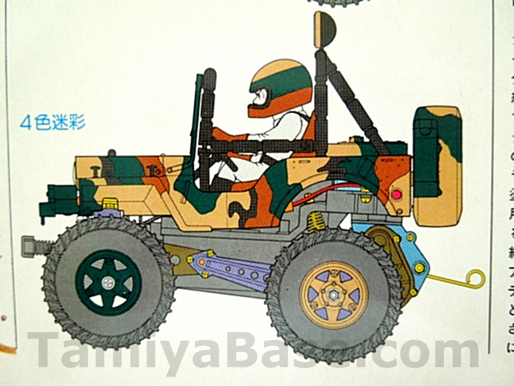
The body set body box has two additional paint schemes show as line drawings – one with red/orange/yellow flame paint (& the driver helmet in horizontal bands of the same colours), and tan/black/brown/green scheme (& driver helmet in horizontal bands again.
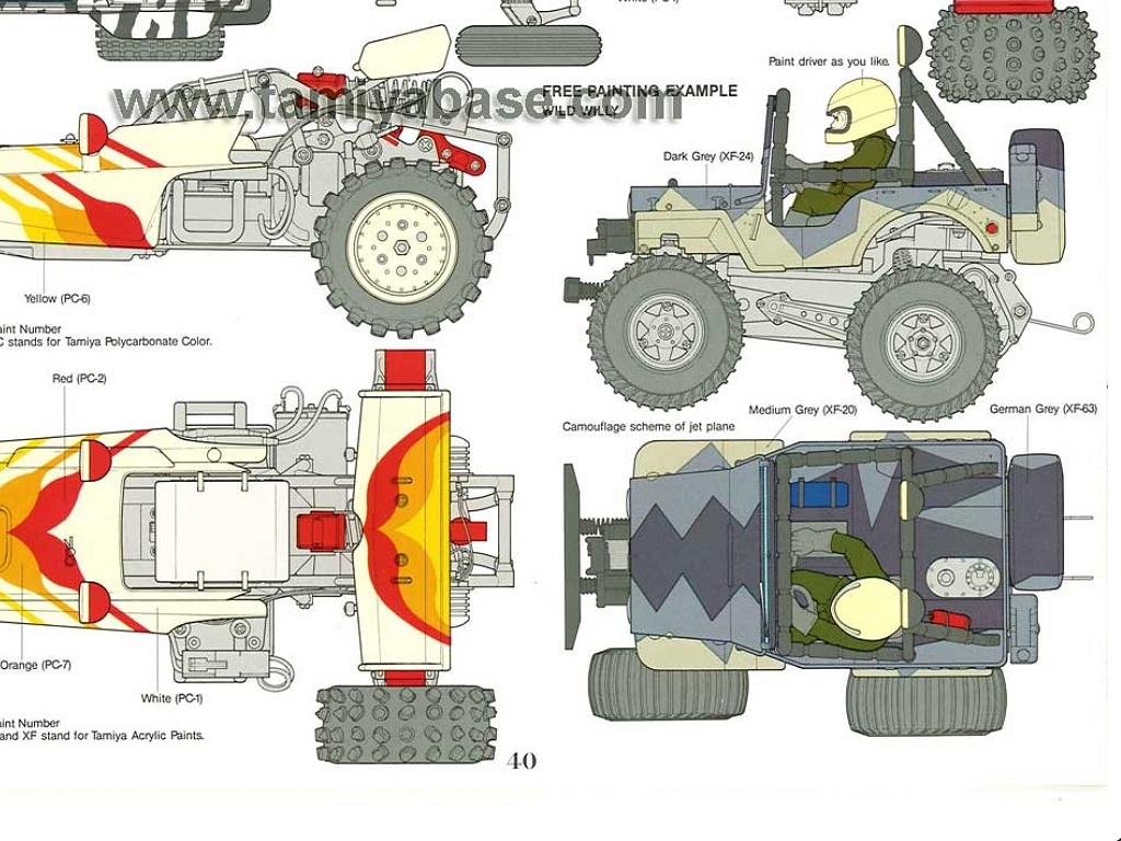
The 1985 & 1986 RC Guide Books have a similar line drawing showing a “jet” paint scheme consisting of 3-tone grey bands with sawtooth edges & the driver in green.
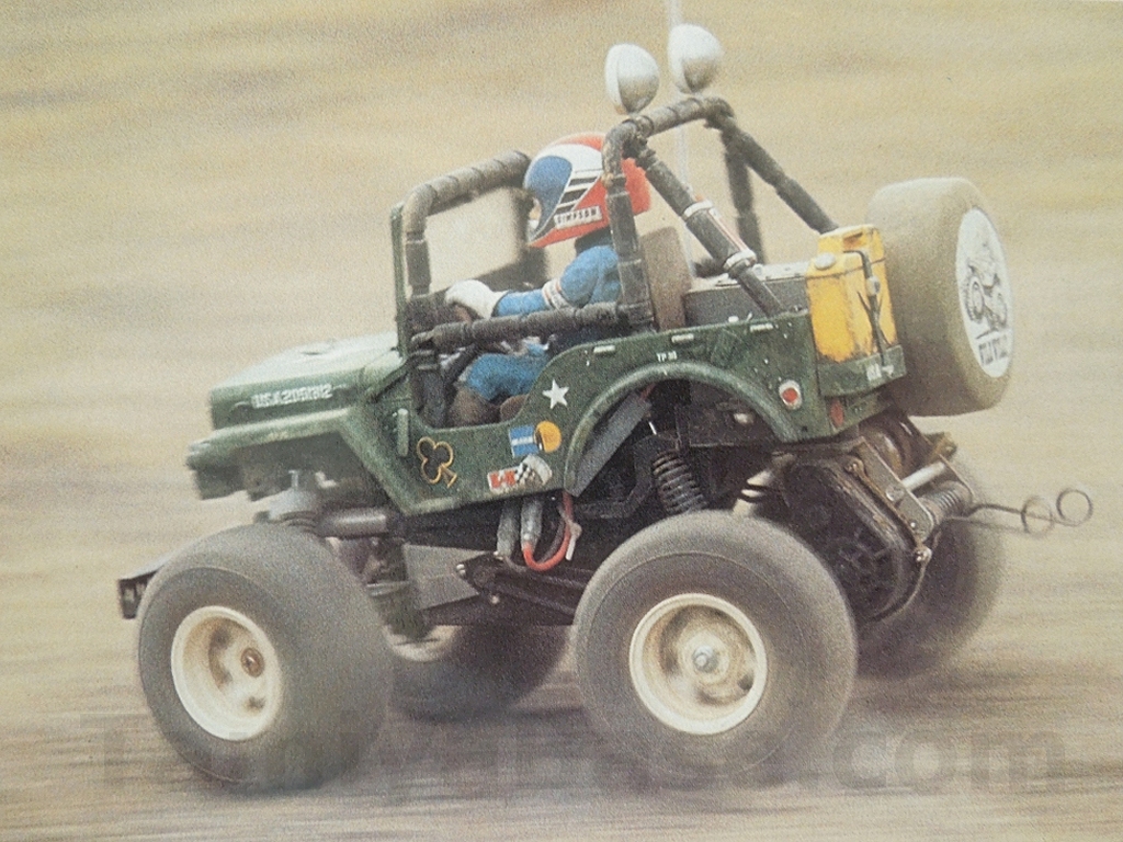
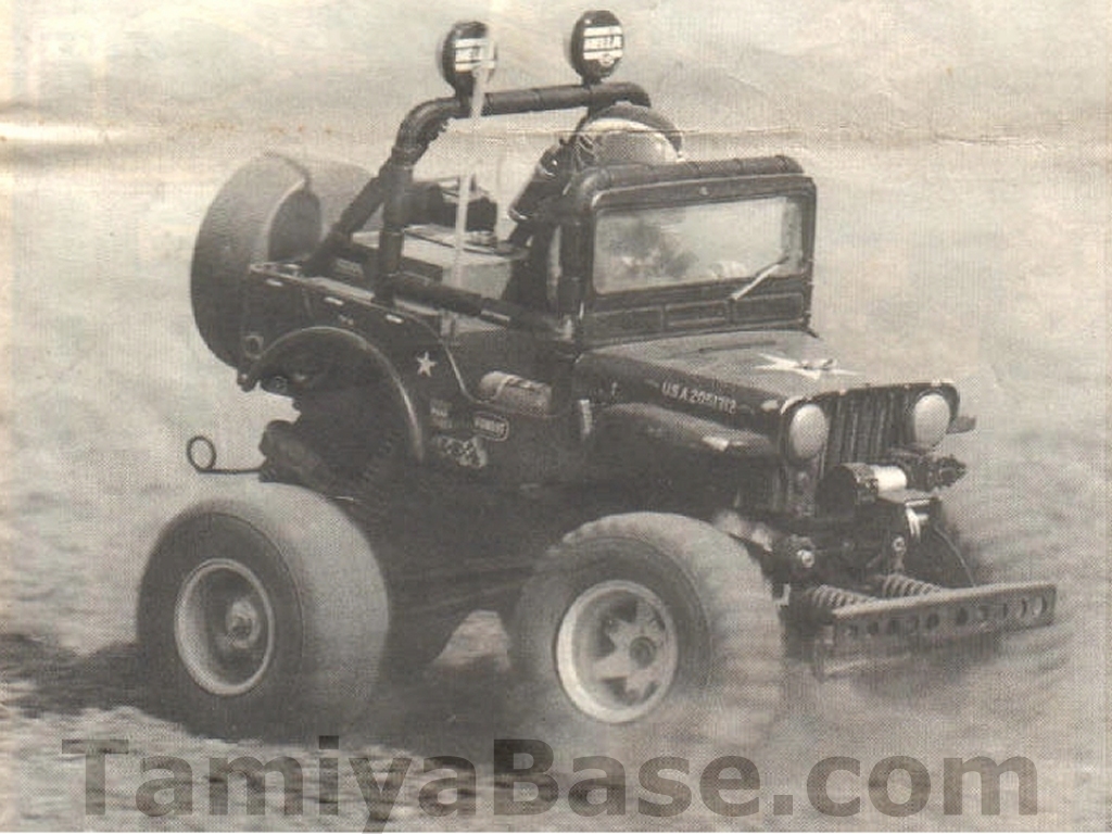
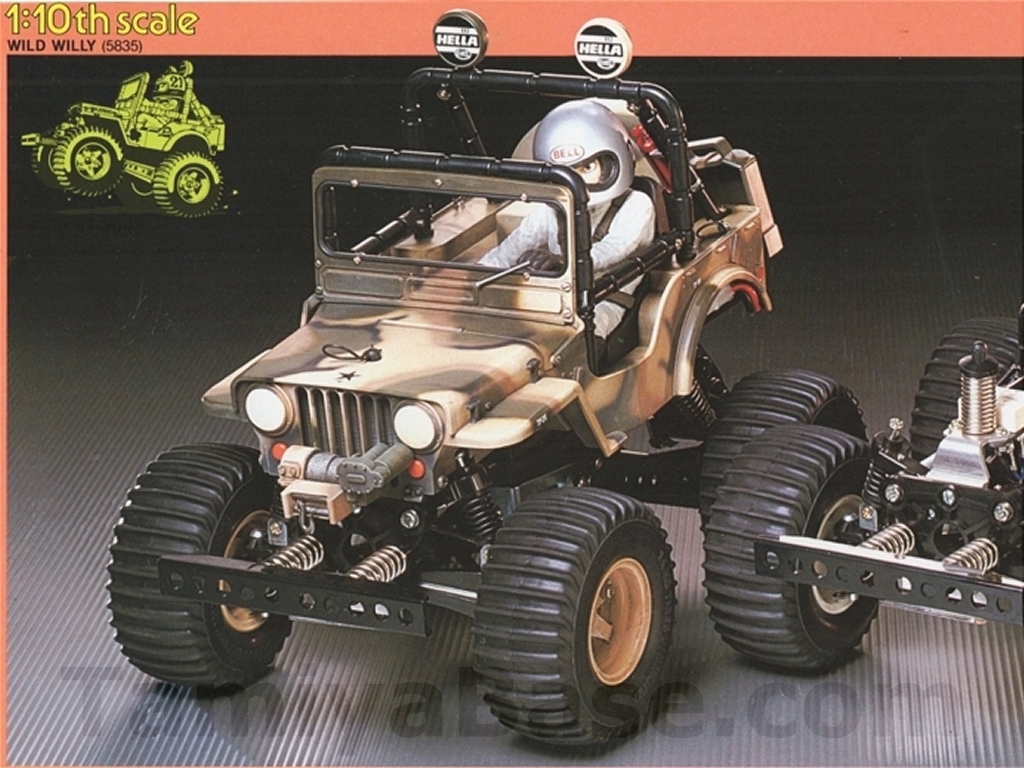
Moving on to the “prototype” SWB Willys (previously detailed here), the first not only has a different driver uniform and helmet paint scheme, but also some brass parts and wheely bars with extra bends, and can be seen in some Tamiya press releases (sometimes presented as “reviews”) and magazine adverts. The second (which could also be the same car, just a bit later) has some decal differences, black rollbar light covers and “production” wheelie bars and is hiding in plain sight on all the vintage manual covers.
The prototype(s) is/are the one (or two) that I’m interested in building as it will just involve a few replacement parts & some paint, but in the interests of completeness there is also a later LWB chassis in green/tan/brown camouflage, one white & one black (or possibly green) rollbar light cover, silver driver helmet and tan painted wheels (seen in a studio shot in at least one of the annual Tamiya catalogues. The running shot in the 1986 Radio Control Guide Book appears to be the same car but with some decal differences on the driver).
Bits Needed
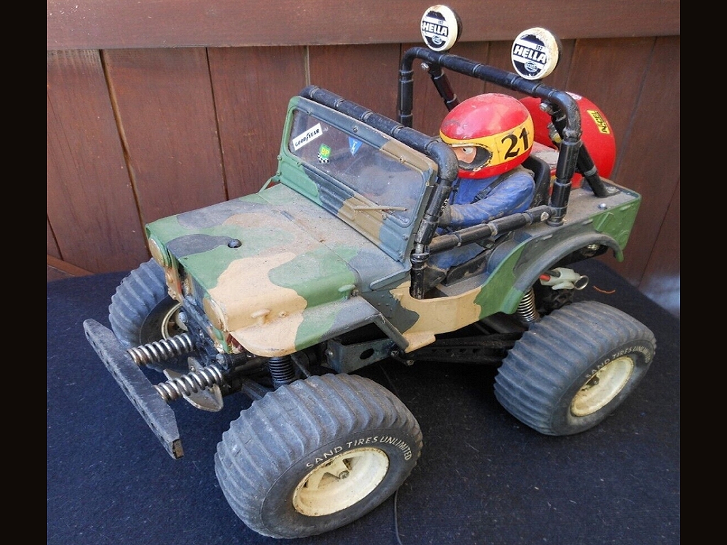
Again, I’d like to stress that no original parts were altered, and the finished car could easily be put back to stock; but obviously the first thing on the checklist was a vintage SWB Wild Willy. My candidate/donor was so below average that it wasn’t an issue to take it out of circulation, but even so, the cost of getting or making one good / complete enough means it’s not something that can be done on a whim.
As well as all the tools, material, paints, replacement parts & fasteners needed for a restoration of any old Willy, I also used:
- short sections of 8, 10 and 12mm round brass bar (and a small lathe to turn them on);
- 25mm x 2mm aluminium strip (a sheet metal press brake would have been nice, I had to resort to bending/hammering in a bench vice & it shows);
- 8mm ball connectors (e.g. from a Super Clod Buster);
- Steel wire coat hanger(s) (e.g. 13 gauge (British Standard Wire Gauge)/2.337mm);
- A new Wild Willy driver sprue;
- A small bit of 2mm styrene sheet;
- Extra Japanese “bullet” connectors.
n.b. some of the steps have been presented slightly out of sequence for clarity.
Bodywork Prep
The front grille panel was beyond a point I felt like I wanted to try to repair so was replaced with a Shapeways one – meaning it could wait until time to primer & paint everything else.
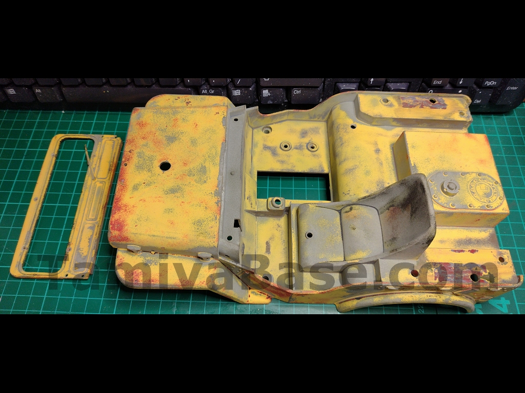
The main body, tailgate, scuttle, and windscreen surround had been previously thickly coated in a badly painted camouflage and an odd metallic blue, over red, over what I think was a well applied yellow, over grey primer. The later layers came off with recycled glass grit in the blast tank, but as I got down to the earlier ones that had been applied with more care, it got more difficult.
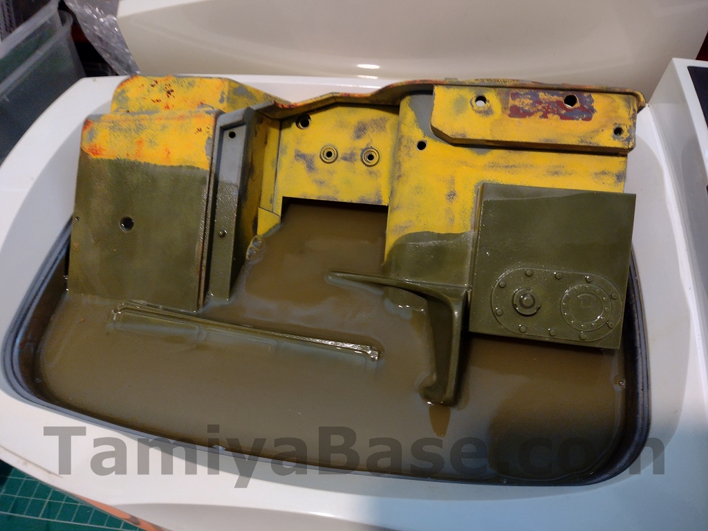
I switched to caustic soda in the ultrasonic tank – this resulted in nicely stripped parts and a nasty brown effluent reeking like fresh Humbrol enamel.
Safety warning: I don’t think any method of paint removal is going to be 100% safe, but some are less safe than others. If you are going to use caustic soda solution, use eye protection – and specifically, indirect ventilated safety googles (for splash protection). Screwfix, for example, have some utilitarian looking goggles for 6.99 GBP, and Toolstation have some slightly better looking and higher spec JSP EVO goggles for 13.98 GBP.
Your spectacles, sunglasses and even “regular” impact rated googles are (potentially) not going to cut it.
The back end of the main body required some small repairs, as did one corner of the windscreen surround.
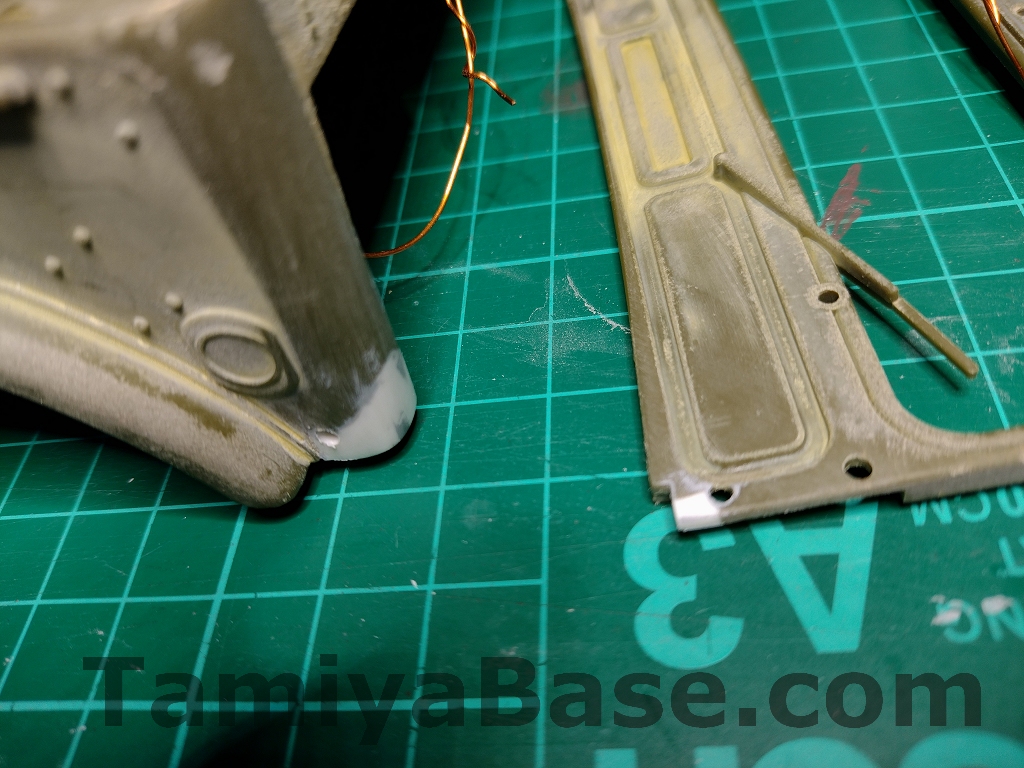
The flat sides and angled rear parts of the roll cage were all original, but the front and rear loops were past it, so were swapped with parts from a later (long wheelbase) vintage Willy. The spare wheel needed stripping and sanding, the jerrycan needed some work too, and as I was already buying some other stuff from Shapeways, I got a back panel insert too.
The windscreen “glass” was cloudy and had decals and paint on it so I didn’t think it would be useable. I took a scan of it & drew up vinyl template so I could make a new one, but after cleaning and polishing the original it looked OK.
Driver Prep
The main body part from a new driver sprue was the only part that got any permanent modification from a stock one – and then, just a small one on a new/modern one to change the neck angle to match more closely what I think it might be on the prototype. This started as a 2mm (IIRC) oval of styrene sheet with an off-centre hole to fit the collar, which was then trimmed down & sanded to form a shallowed wedge in the front.
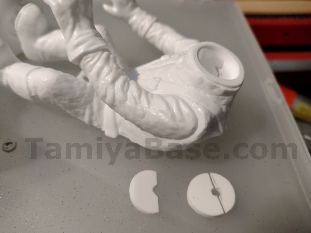
The original driver got stripped, primed, and put aside for the time being.
Chassis Stripping/Prep/Repair
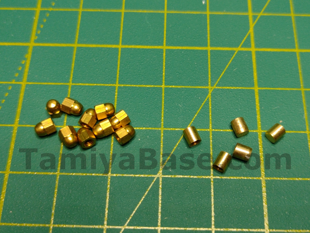
Many fasteners were missing or incorrect, some having been replaced with split pins. Also missing was one of the rear spring top cups, and the steering servo arm pip – but I already had a few of those turned from brass M2 acorn nuts.
As per usual, the diff had been lubricated with an excess of many kinds of grease and oil BITD, so the resulting Marmite and lime jelly looking mess had to be scraped out. All the diff gears and one of the idler gears are still available as they’re also used in Tamiya’s rolling rigid axle as found in the Lunchbox & so on) so I replaced them.
Initial ultrasonic cleaning of the chassis parts was uneventful, I didn’t even lose any of the tiniest parts for once. The aluminium got parts a once over with wet & dry paper to remove any remaining oxides, and the pink/copper plating the brass parts inevitably got covered with was polished off with Autosol. The most visible of the plastic parts got a light restoration with Novus plastic polishes.
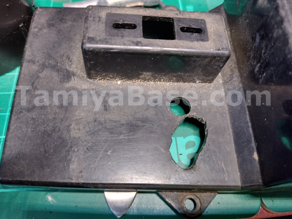
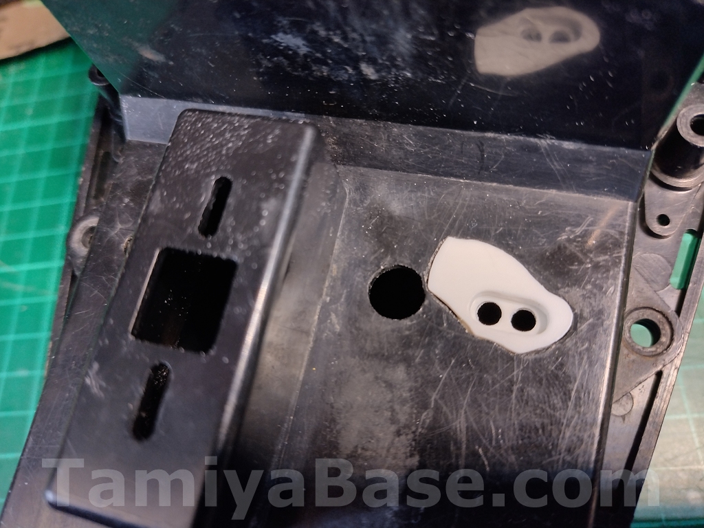
Although the mechanism box lid was present on the donor chassis, it had been butchered to accommodate some crimp on Lucar connectors (possibly very recently) so needed repair. I Dremelled an odd-shaped bit of styrene sheet to fix the hole, cut an oval in that & fixed another bit on underneath. I bonded it on with 2-part epoxy adhesive but the X-1 Black paint I finished it with was not a great colour match, as you'll see later.
The plug for the resistor wires is the same as used on the vintage 3-speed gearboxes – so 10 years ago (with the re-release of the Bruiser and Mountaineer) they were no problem, but seem to have become unobtainable again, so it’s lucky I had a spare. A new rubber switch boot came from a re-re SRB parts bag.
I drilled out the Shapeways SWB front shock mounts to fit M2 thread inserts. I had a set of wheels and tyres in better condition than those on the car, but the wheels had previously been painted so that needed stripping off.
Electrics
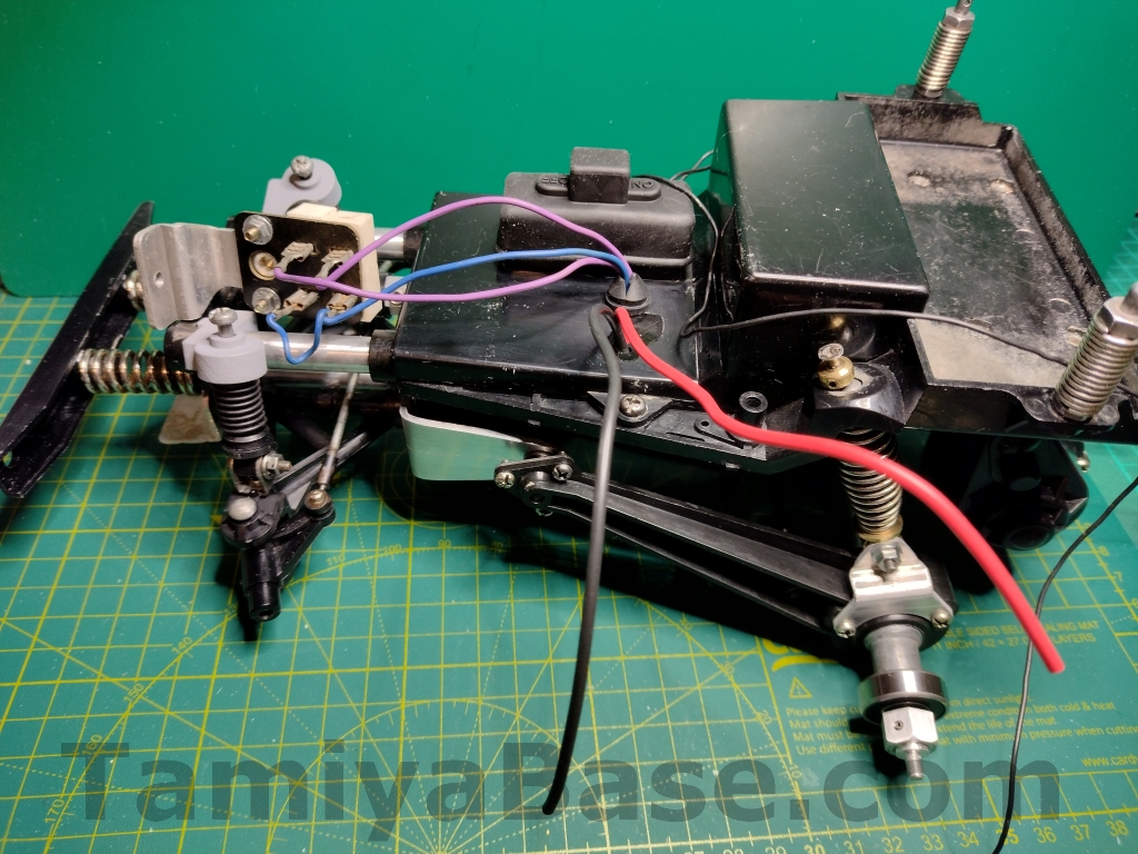
The electric parts were grim, the motor also needed new wires. Unlike the production models, the prototypes use the now standard “Japanese” (3.9mm) bullet connectors rather than splices – and the prototype does not have any heatshrink on the motor.
Someone had used electrical tape instead of the recommended Heatshrink tubing, the baked-on residue from that needed Tar and Glue Remover to fetch off. The mechanical speed control (MSC, or “switch” in the manual) also needed new motor & battery wiring, and a poor filling in a hole near one the low-speed contacts tidying up.
The mk.2 Acoms servos & receiver got a clean with baby wipes + Tar and Glue Remover where needed.
The 4xAA holder had a lot of alkaline crystals & verdigris on the contacts from past battery leakage. This fizzed off with citric acid (there’s an article on doing this, and one on using lemon juice to a similar end if you’ve not feeling quite as brave).
I do like to maintain the illusion – to myself if no-one else – that my cars are ready to go, only needing batteries. This meant buying an Acoms mk. ii transmitter to match the radio gear that came with the car. It was “untested” (and of course, didn’t work) but was soon up & running without too much effort. I’ve had enough asides already in this piece, but it did get me thinking that a lot of apparently “dead” vintage transmitters could be resurrected without much electrical knowledge, so there may be an article on that type of “fix” coming soon.
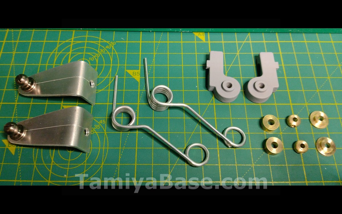
Making The Alternative Parts
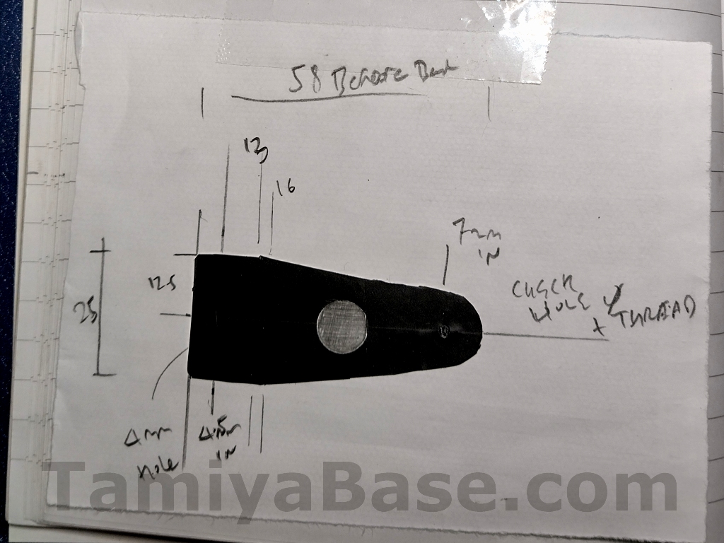
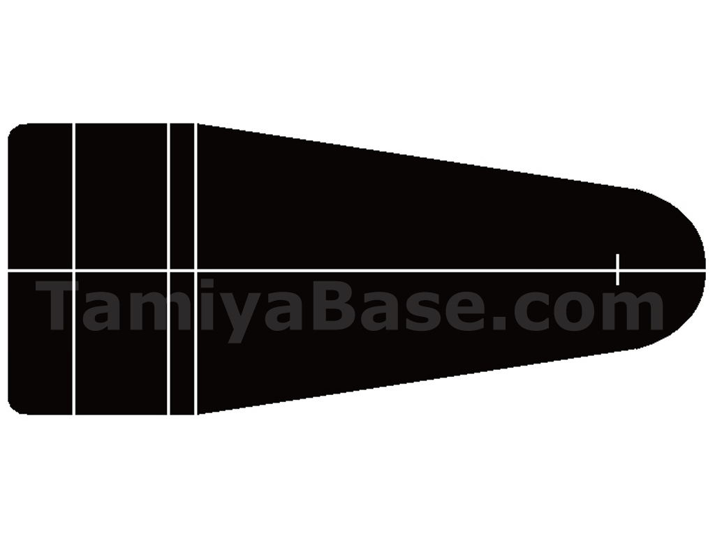
I started by working out what I needed for the “prototype” rear arm stays by sticking masking tape to the outside of an existing bracket. After peeling it off and scanning it, I tidied up the result to give me an image I could use to create templates on a vinyl plotter/cutter.
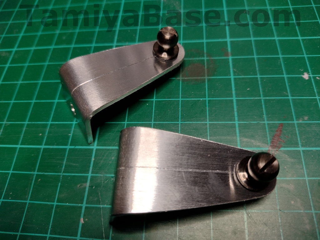
Getting an aluminium strip the correct width (25mm) but too thick (2mm v 1.8mm) seemed easier than more cutting from a plate the right thickness. After a bit of scribing/sawing/drilling/thread tapping/filing/bending to shape I had passable new brackets, but using a press brake rather than the vice I used would have given a better result.
The 8mm ball connectors are those used in the Super Clod, and needed some thread grinding off to make them level with the top of the M4 flange nuts I used on the inside.
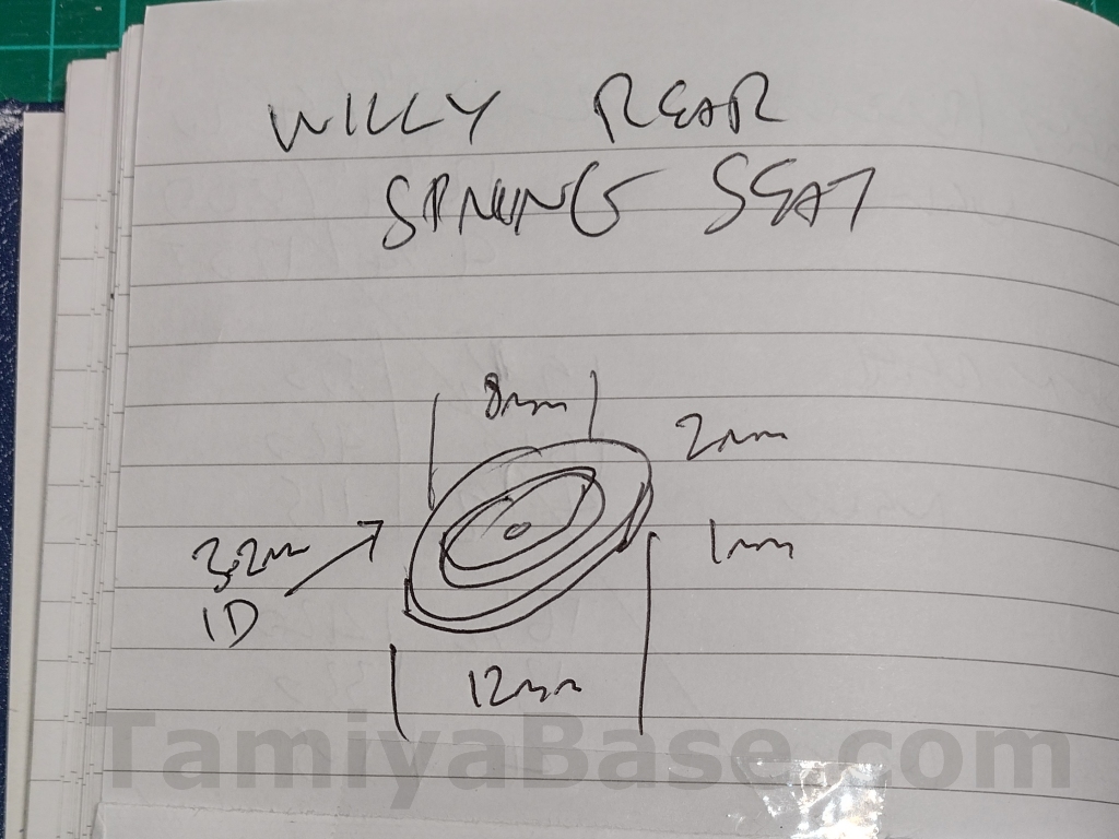
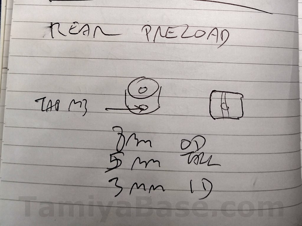
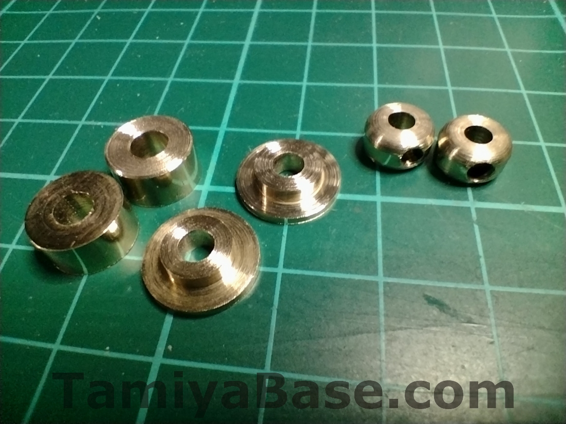
I sketched up the front wheel spacers, rear spring bottom seats & rear preload collars & turned them from 10mm, 12mm and 8mm round brass bar respectively, then drilled and tapped M3 threads where required.
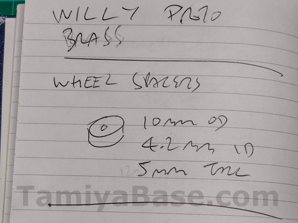
I know these look rough – but they only had to be good enough to help me make the replacement parts while also looking at the original parts for reference.
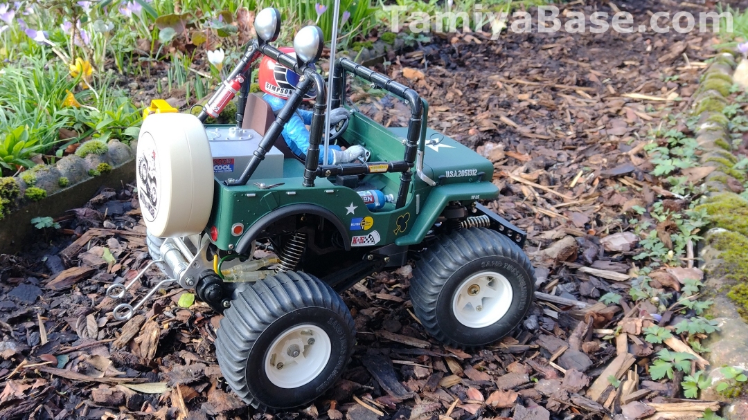
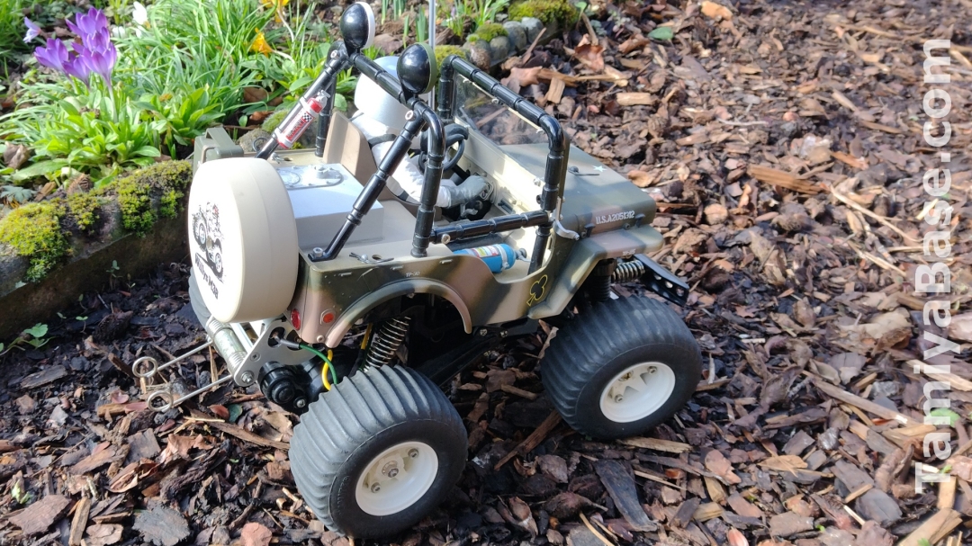
I made the wheelie bars from wire coat hangers, the method was as the article here but with an initial 90 degree bend instead of 135, plus another bend on the exposed side to get the overall angle correct. I ruined the initial 3 or 4 attempts using an inadequate clamp on bench vice before giving up & using the much bigger one out in the shed.
I also had a go at making the reverse bodyclips as seen on (at least some of) the SWB Willy … seems I lacked the skills and/or tools to make them in 1mm brass, so getting them right in the 1.2mm steel required would have been out of the question.
Initial Painting (Outdoor)
Despite the vagaries of the British Summertime and having no facilities other than a couple of bamboo canes close to the rafters in an old shed, I have to spray anything that needs an aerosol (and even the larger of the bits that can be done with an airbrush) outdoors in the “better” months of the year.
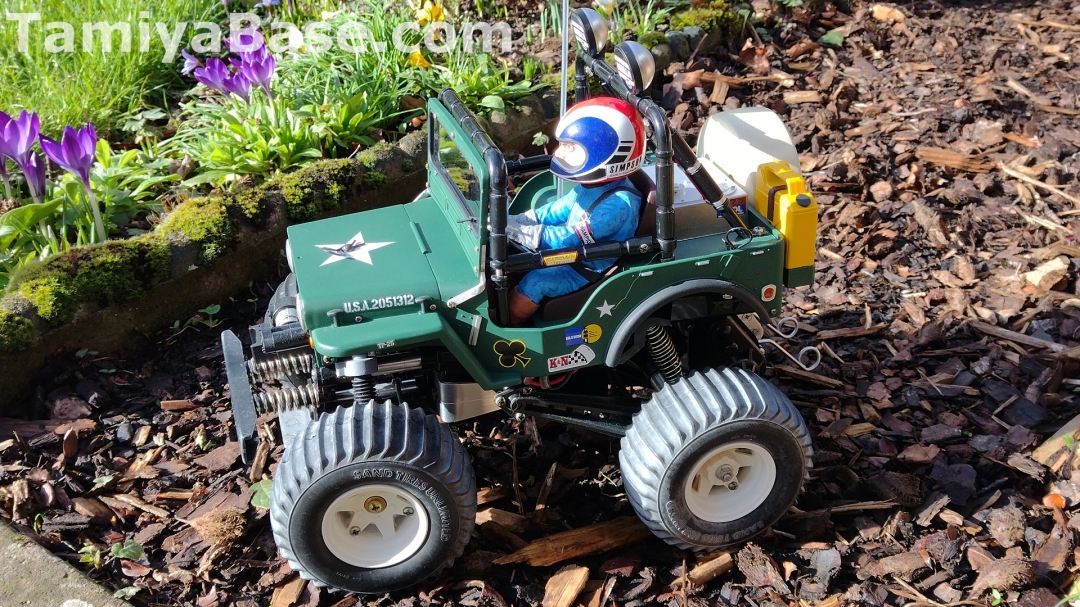
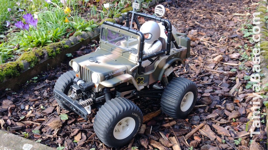
The body work got a rub down, a thorough prime with Hycote Grey Plastic Primer, another light rub down, and finally, Tamiya XF-70 Dark Green 2 (IJN) airbrushed on. IJN meaning Imperial Japanese Navy (so WWII), but I wanted to use it as while it’s still a military green, it’s obviously different from the bare plastic, Tamiya TS-28 Olive Drab, TS-61 NATO Green, XF-67 NATO Green, XF-68 Olive Green, or any of the three flavours of Humbrol 155 Olive Drab Matt that you usually see Wild Willys in. It’s a dark, Christmassy green like the plastics of late Acoms mk. ii radio gear.
I had much less paint than I thought but having mixed it 50:50 with X-20A thinners I managed to airbrush two coats from multiple angles on everything that would be seen, and even the underside got a light fill from the very last dregs.
After extensive taping up, the lights on the rear rollbar and the fire extinguisher portion of the left rear rollcage support got coat(s) of White Plastic Primer, as did the spare wheel cover, jerry can and insert, all the visible parts from the set of wheels, the driver figure(s), and the Rollbar light covers.
For convenience I used Hycote acrylic aerosols in “Chrome Look”, Post Office Van Red, Ford Sierra Beige, AA Van Yellow, and VW Alpine White respectively, with Clear and Satin Black to finish the two sets of Rollbar light covers differently.
Detail Painting (Indoor)
The nitrous oxide bottle was airbrushed with a mixture of X-14 Sky Blue & X-23 Clear Blue, with the rest of the body details being brushed on X-11 Chrome Silver, X-26 Clear Orange, X-27 Clear Red, XF-85 Rubber Black, XF-9 Hull Red and XF-70 Dark Green 2 (IJN) as appropriate.
The radiator (previously sprayed with Hycote “Chrome Look” got a light wash of the black to bring out the details.
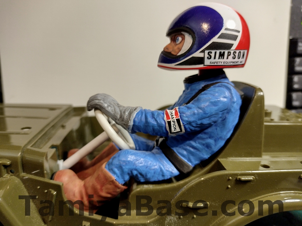
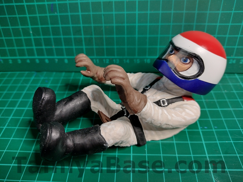
The driver figure was done with Vallejo acrylics as I was trying them out at the time (love the range of colours and the how to guides, not impressed with their apparent lack of robustness and how the clears go on, and they don’t play well with Tamiya acrylics), the face(s) have an awful lot of shades and steps but they’re definitely a level above what I’ve managed before. Paint on the drive body is a mid-blue suit with white brassard (armband) on the left sleeve, black belts, grey gloves (with a black wash), and brown boots.
The helmet is quite different from that seen on the “production” models, with the blue, red and clear all being airbrushed on. The black stripes were cut from satin black self-adhesive vinyl, the Simpson decals came from an MciRacing repro sheet.
There’s no visor pictured on the Wild Willy prototypes, so I didn’t fit one.
The original driver got brush painted for the most part (with airbrushing on the red and blue sections of the helmet) in the standard colours, and a new visor cut from 140 micron (0.14mm, or 5.5 thou”) clear acetate sheet – bonded on with Pacer Formula 560 Canopy Glue. I’m going to have to tie a label on him, so I don’t accidently use him in a different project or sell him.
Body Assembly
There’s not a whole lot to note here other than the Shapeways grille needing a bit of fettling to fit the headlamps and radiator, the back of the jerrycan was an excellent push-in fit, and thanks to the change in head angle, the driver can only have the most peripheral view of the way ahead.
Getting the screw and nut to line up to secure the driver whilst juggling the steering column and wheel was as much of a lottery as usual – sometimes they go right in with no fuss whatsoever, but this occasion was one of the times when you wonder what on earth you’re doing wrong.
I also misplaced the original windscreen so had to make a new one from 0.5mm Lexan sheet. After finishing the assembly, of course I then found the original.
Chassis Assembly
I followed the manual for the build-up of the chassis, entirely omitting threadlock and only using a small amount of ceramic grease in the gearbox(es), fitting new bearings and the replacement “prototype” parts as they came up.
I turns out I hadn’t done quite as much forward planning as I thought I had, and had to hit my spares box (and, more often, a dismantled & cleaned LWB Willy chassis you can see at the end of this piece) for some missing fasteners & parts.
Steps 1, 2 & 3 on page 3 of the manual see the start of the steering and front suspension, and the first of the replacement parts go on - the Arm Stays.
Steps 4, 5 and 6 on page 4 complete the front suspension, including the always fun juggling of the front bulkhead, front arms, aluminium pipes, and the fasteners needed to holder them all together. This also sees the next replacement parts – the grey front strut tops – go on (part numbers J2 and J6).
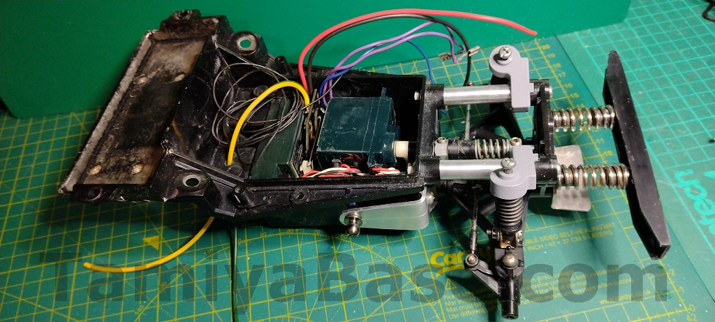
Page 5 (steps 7, 8 and 9) are the installation of the mechanical speed control and most of the radio gear. The Acoms mk.ii set is a bit of a tight squeeze in places, but I didn’t have to resort to any of Tamiya’s suggestions (filing off excess solder from the underside of the MSC, leaving the crystal seal off the receiver, cutting off one side of the screw fixing brackets from the MSC servo) to make more room.
Although the battery tray will be hidden by an old 7.2v “hump” pack, I really should have polished it up before assembly … IIRC I did go back & do it later, but it’s just as ugly through the rest of the pics here.
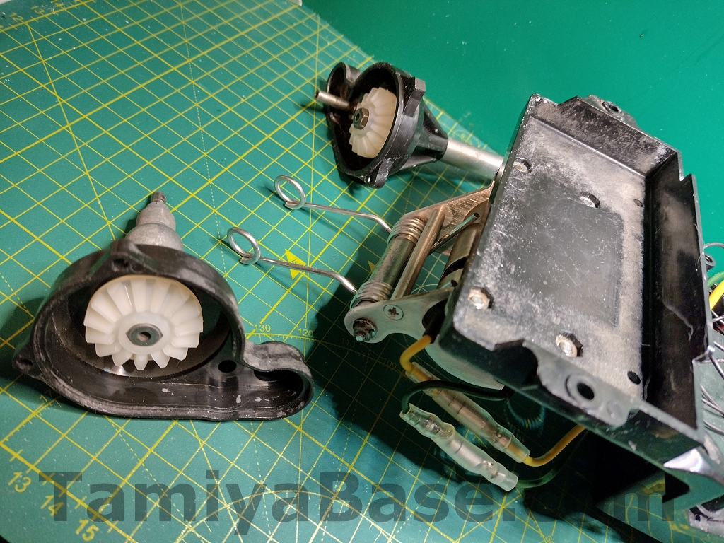
Page 6 (steps 10, 11, 12) deals with the motor fitting (including the replacement wheelie springs) and starting on the diff housing. I used heatshrink tubing as suggested on the motor contacts but omitted the large bore grey tubing over the motor body, as shown in the “prototype” photos. I used Japanese “bullet” connectors (tinned, crimped and soldered) on the motor wiring instead of the splicing / soldering / heatshrinking as detailed in the manual, and attempted to arrange them as per the prototype. You can also see the new diff outdrive gears here.
Steps 13 to 15 on page 7 finish off the differential housing, attachment of the rear arms, lower suspension fittings, tie rods, rear wheel bearings and hubs.
Although the f5 parts (“Spring Pins”) appeared to be in good condition in this case, I’ve often found that they’re broken, rusted, or entirely missing on vintage Willys, so I replaced them with 2mm x 12mm stainless steel roll pins. They have a slot along their length rather than the fine teeth of the original part and can need some gentle closing up with pliers (especially on the end to be inserted first) before fitting to ease their path.
The short lengths of rubber tubing on the tie rods were past their best so I cut some from a new length of hose – specifically 2.5mm ID (inside diameter), 5.5mm OD (outside diameter) NBR (nitrile butadiene rubber) unreinforced/smooth fuel hose.
Note the inadequate polishing of the rear arms :(
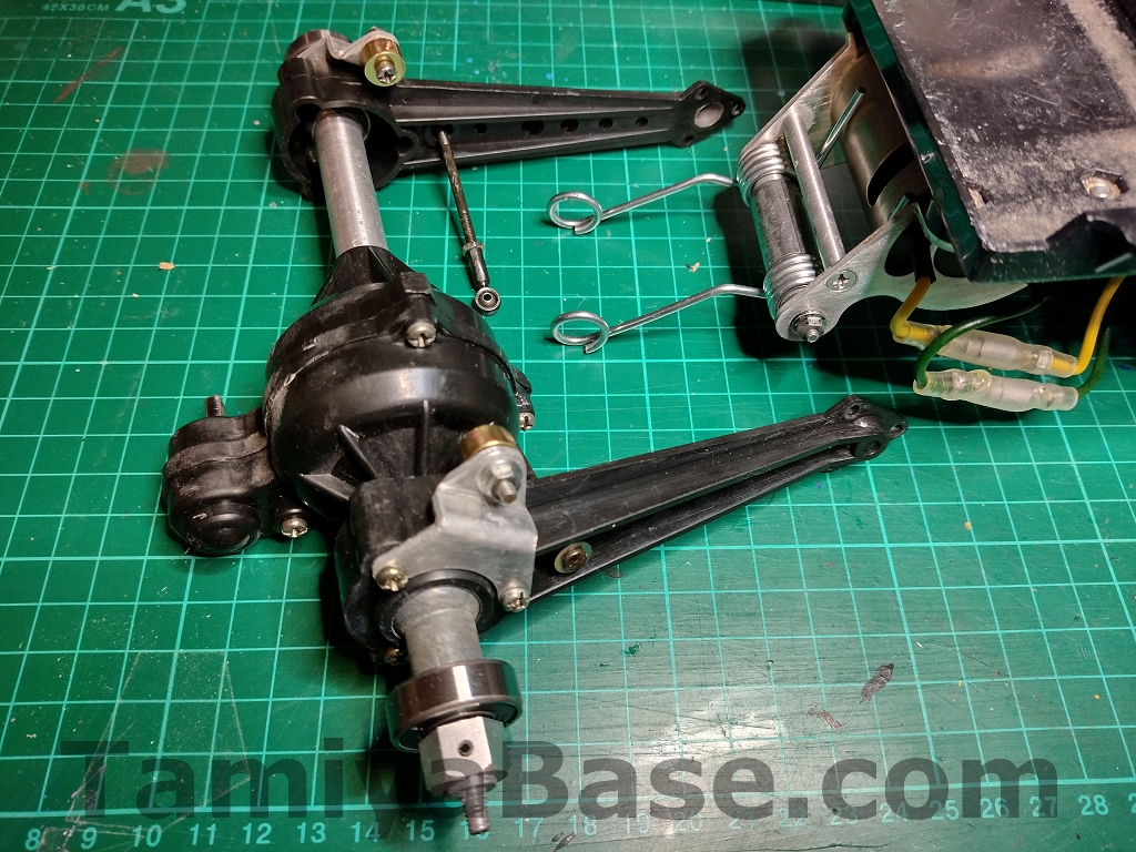
Steps 16 to 18 (page 8) cover fitting the diff housing, plus the assembly of the reduction gearbox and its connection, via a now very shiny brass universal joint. At least I remembered to polish that.
I found one of the M2 screws holding the tie rods in had stripped the plastic out of the mechanism box point, so had to use a V-coil thread insert to fix it.
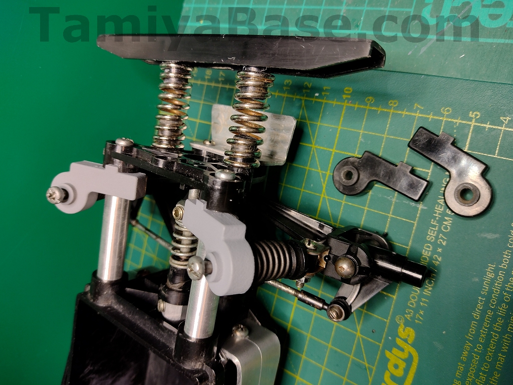
Step 19 (page 9) covers fitting the rear springs – along with the replacement brass lower spring seats and preload collars, which are both machined aluminium parts on a production SWB Willy.
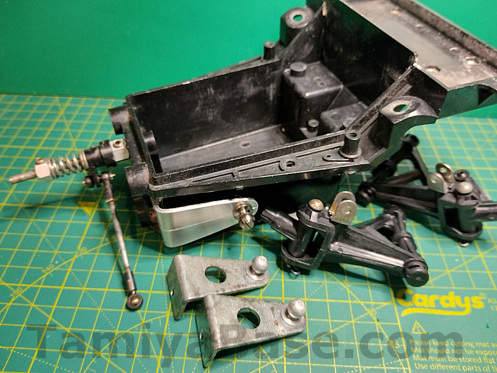
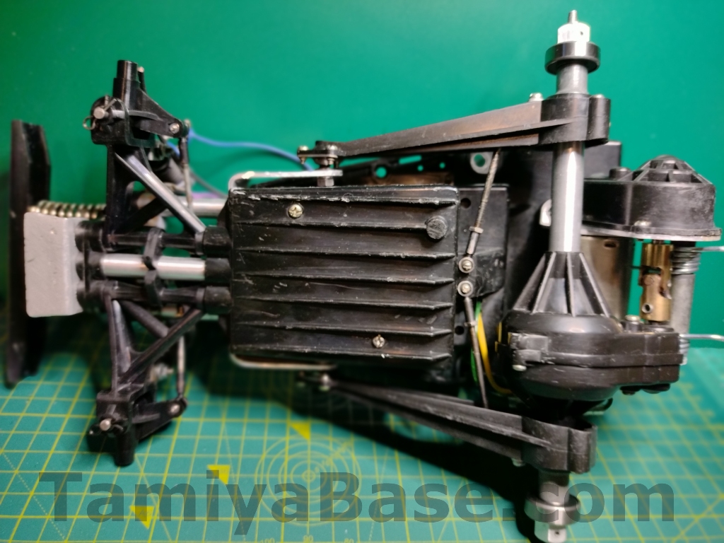
Steps 20 and 21 are fitting the mechanism box lid, rear body posts and putting together the front body post / speed control resistor assembly.
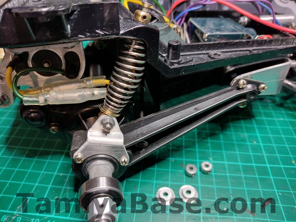
I don’t seem to have a photo of Page 10 (steps 22 and 23), but they cover assembling and fitting the wheels (along with the replacement brass front wheel spacers) and the last few chassis details, including the antenna tube and battery connector. As with the motor connection earlier, I used bullet connectors instead of the splices of the production models.
Steps 24 to 30 across pages 11 to 13 cover painting and assembling the driver figure and body, all of which I’d already done, apart from finally clipping the body on.
Ever since the body of my first RC kit (a Grasshopper) didn’t come out as I would have liked I’ve advocated (and often followed) finishing the body before starting on the chassis – that way it can take as long as it takes and doesn’t get rushed.
Conclusion
I’m quite happy with how that all turned out, and that it can be put back to original by me, or if desired by any future owner.
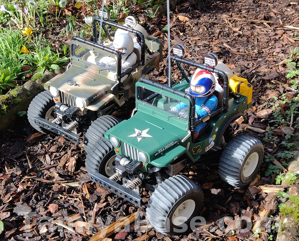
If you think this has all been a bit nerdy and pointless, you’re missing an important point – it’s not quite the same as another Wild Willy and is therefore easier to justify holding on to. On the same note, the other Wild Willy shown here is a vintage LWB chassis with second best bits on it, with the catalogue airbrushed camo paint scheme on a heavily modified Wild Willy 2 body.
__________________________
Written by TB member Jonny Retro