That sounds intresting....black plate for SWB and white for LWB That's exactly what i have on my WW. (see my SWB resto thread) Manotas Proud owner of the Bruiser Family
|
|
Please Log in to join the conversation. |
|
Thanks Another theory bites the dust
Really? You got black plate = SWB, white = LWB from WB's post? Actually, I don't suppose it's any worse than my assumption that black plate = LWB/Wheeler & white = SWB as that's the way round mine have been ... or the similar assumption on wire length I think we've already concluded that both all M38s & wheeler have black resistor plates, I don't think wheelbase defines the colour... IMO any with a white plate but the "short" wires means Tamiya had probably run out on a given day & put a white plate in, any with a white plate & longer wires is probably either a non-car specific Tamiya spare, or originally intended for The Frog. |
Please Log in to join the conversation. |
Hi Jonny,
As promised the switch stay pictures for comparison. Note that the one with the switch is the LWB ( i know you know that! ) I had to compress them in order to put them on here, so just let me know wich one you want, and i'll be happy to send it to you in a full format. If you you need pictures from another perspective, dôn't hesitate to let me know. Proud owner of the Bruiser Family
|
|
Please Log in to join the conversation. |
|
Thanks ... but those aren't "Switch Stay"s, those are "Mechanism Box Lid"s These are Switch Stays
|
Please Log in to join the conversation. |
Ewwwwww sorry for that !I feel so dumb ha ha ha ha I'll take the right pictures later on... Proud owner of the Bruiser Family
|
|
Please Log in to join the conversation. |
|
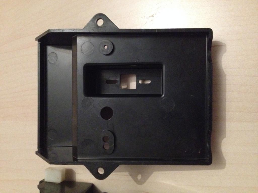
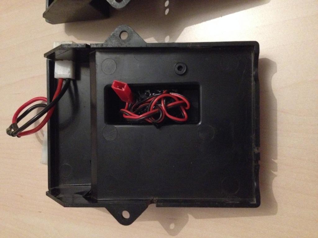
Rewiring done, I can finally get on with rebuilding these
The covers of the manuals for the two versions are identical, but the insides are quite different in places on closer inspection. 
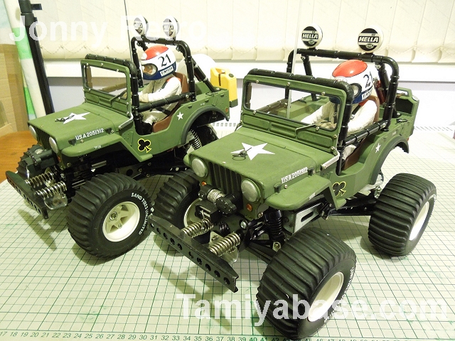
Page two has some differences, the main one being that the SWB manual has a description of the 1:1 Jeep. Page 3 (which mostly covers building the servo saver) is subtly different, including revisions to the drawings to accommodate the part changes... 
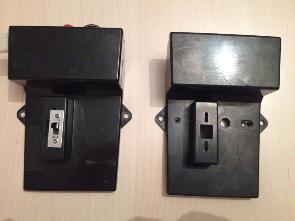
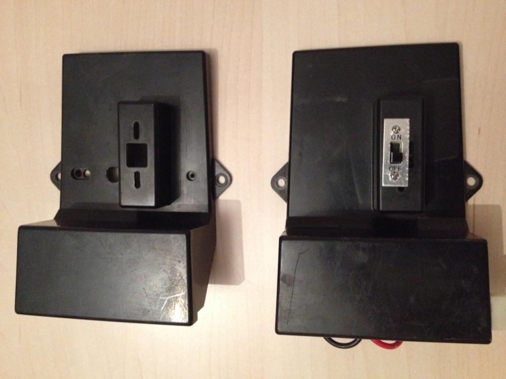
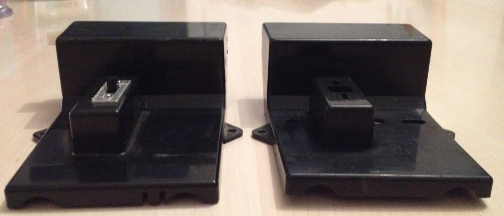
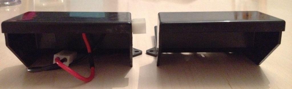
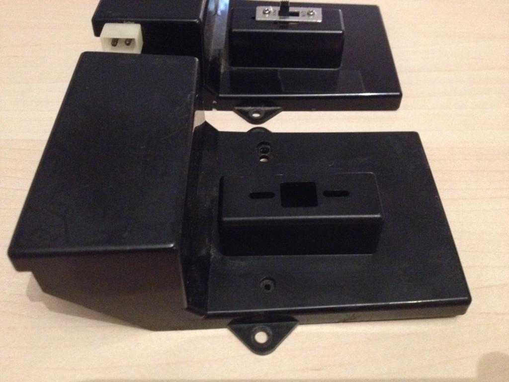
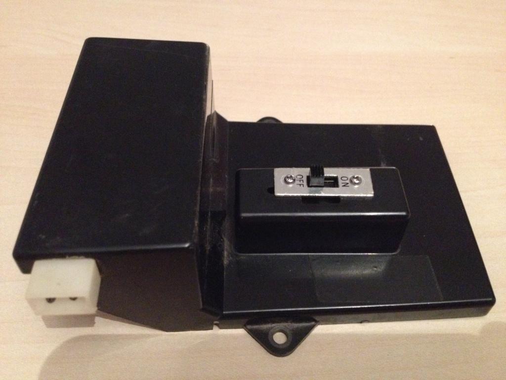
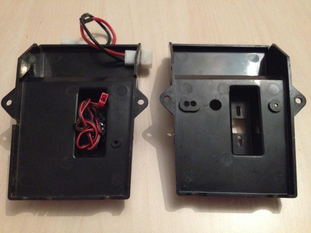
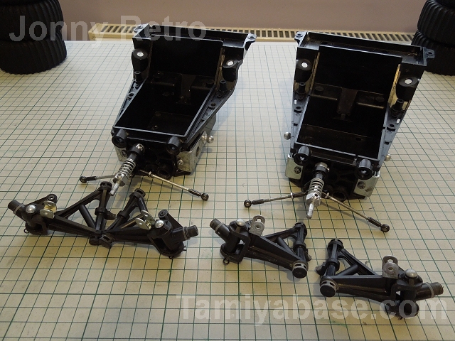
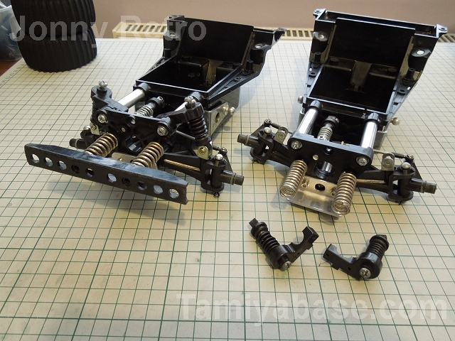
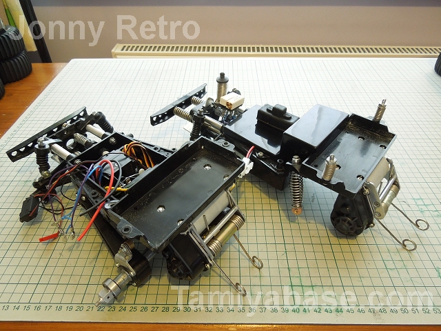
(SWB is on the left, LWB on the right in all these pics BTW) Here's is where it starts getting a bit different - Page 4 is pretty much completely redrawn, the parts are put together in a different order (the front end juggling - trying to align 3 tubes, two suspension arms, the servo saver shaft, the bulkhead & chassis - seemed slightly easier on the LWB, or maybe it was just practice ), but less gets done on the page: 
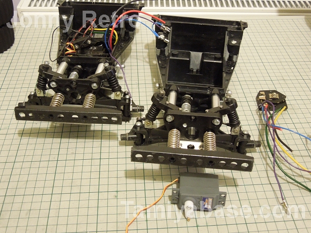
page 5 & the LWB hasn't quite caught up - it should have the MSC & servo attached to the switch stay, but I only had one SWB 
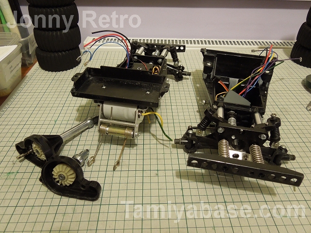
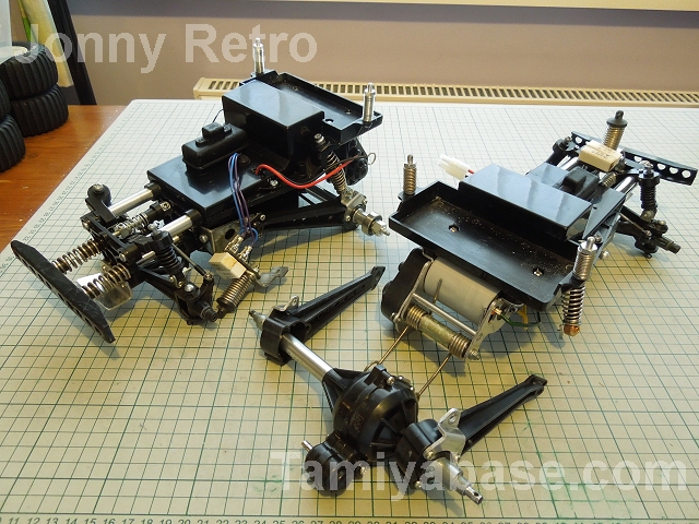
Page 6: SWB way ahead with the Motor Base built up & diff. started; LWB you'll have to imagine the MSC & servos installed properly 
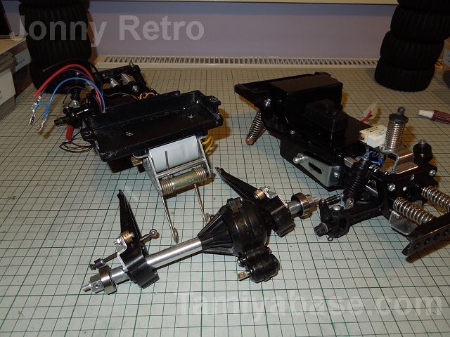
Page 7: SWB diff case finished with rear arms & radius arms fitted; LWB goes off at a complete tangent ... 
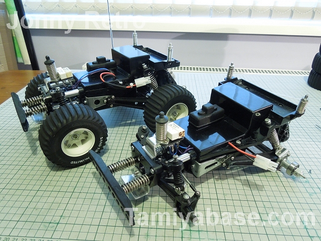
Page 8: SWB - gearbox built & attached, along with rear axle; LWB getting back on track, but still behind... Page 9: SWB gets bits done that LWB did earlier; LWB vice versa... .... |
Please Log in to join the conversation. |
|
The following user(s) Liked this: Dam
|
Please Log in to join the conversation.
Last edit: by Jonny Retro.
|
Really great work JR they both look awesome, you know when I hear long & short wheel bases I expect it to be more dramatic Top stuff mate
If you can't fix it with a hammer, you've got an electrical problem mate
|
|
Please Log in to join the conversation. |